When it comes to 3D printing, the orientation of your print can have a significant impact on strength, aesthetics, and functionality or ease of printing. The folks at Slant 3D have found that printing enclosures at a 45° provides an excellent balance of these properties, with some added advantages for high volume printing. The trick is to prevent the part from falling over when balance on a edge, but in the video after the break [Gabe Bentz] demonstrate Slant 3D’s solution of minimalist custom supports.
The traditional vertical or horizontal orientations come with drawbacks like excessive post-processing and weak layer alignment. Printing at 45° reduces waste and strengthens the end product by aligning the layer lines in a way that resists splitting across common stress points. When scaling up production, this orientation comes with the added advantage of minimal bed contact area, allowing the printer to auto-eject the part by pushing it off the bed with print head.
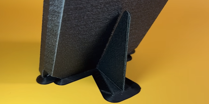
To keep the part stable while printing in this orientation Slant 3D designed a fin-like support structure attached to the back of the enclosure with small sprues. This wastes significantly less time and material than auto-generated supports, and snaps away cleanly, leaving behind minimal imperfections that are easily addressed. To improve aesthetics and hide layer lines, Slant 3D also recommend adding texture to the external surfaces of enclosures. On 3D printed parts this detail costs nothing, while it would have added significant costs to injection molded parts.
We’re intrigued by this creative twist on 3D printing’s capabilities—proving once again that a simple shift in perspective (or in this case, orientation) can unlock new design potentials.
Slant 3D use FDM 3D printing for mass production [Gabe] even hosted a Hack Chat on the subject. They have come up with a number of innovative design tricks which are also useful for the hobbyist. These include improved corner brackets, robust living hinges and better alignment features for 3d printed assemblies.


It’s a design technique being well presented. Why did you add a zero-value comment? It’s no better than “Just go buy one”.
Generally, something made with less of a given material is weaker, but in this instance, printing in such a way does not cause the final product to be weaker, despite requiring fewer resources than one made in a more conventional orientation.
Tough crowd here. Thanks for sharing the tip.
If you believe that, then I have a pedestrian bridge over SW 8th street I’d like to sell you.
Wouldn’t a 45 degree angle put the edge of the cuboid against the build plate instead of the corner?
This makes sense – and the video helps get the message across clearly. Well done.
What happened to the lid of the box on minute 5:14. The lid does not close the box. It looks like your print is not that good, right? The Author haven’t explained why he printed the lid in 35 degrees while he said the perfect angle is 45 degrees.
Yes it should be “and”
Incorrect
To you, I guess?
Interesting, but might requires a relatively long Z axis and accurately calibrated X, Y, and Z axis orthogonality- probably not suitable for most hobbyist grade printers. It would have been nice to see him measure the dimensions of the final prints to see if they matched his drawings.
Possibly. But there’s another advantage of printing at an angle. You can get a longer length in one dimension. For instance, assume you have a built volume of X, Y, and Z all having a maximum value of 200 mm. Now if you want to print a box that’s 25 mm tall and 200 mm deep, you might think the maximum width would also be 200 mm. But if printed at 45°, the maximum width becomes 257 mm.
Instead of adding the support structure to the CAD model, one could use support blocker on the slicer to limit the amount of auto generated support. I’ve done this with my models. The gap mentioned can also be controlled for by the slicer. Usually it’s a setting in the advanced menu of the slicer.
One should note that the 1st layer cross section of the main body needs to be sufficiently largely to prevent peeling or shifting when printing. I didn’t see a mention of that in the video. His model has a chamfer to provide good 1st layer adhesion. So he understands the principle but maybe forget to mention it.
.. And get crack diagonally. Bad idea – better to model thread or make mount “peaks” with holes on back plate.
Diagonal cracks are far less likely given how it’s loaded.
Then why didn’t you share it back then?
In any non-dying hobby there is a constant influx of new people who need to rediscover old stuff.
Agree. Aesop was a wise man.
I’ve got to say, I really enjoy Slant3d’s content, they obviously have skin in the game, they’re not hiding that fact, they’re actively sharing what they’ve learned and getting this information out is key for a lot of people, whether you’ve known this stuff for 10 years or it’s a TIL moment.
It increases waste due to the need for supports though?
exactly what I was thinking.
As in: “Printing at 45° INCREASES waste but strengthens the end product by aligning the layer lines …”
The flat orientation needed no supports, but the other two more vertical orientation filled the interior with supports.
I really wasn’t expecting the single support in the middle. I expected supports on the sides to bridge across. I can’t quite wrap my head around how this works.
At 45°, You don’t actually need any supports. There is no bridging in this type of print. The subsequent layer lines overlap the line below it sufficiently enough (probably about half the line width) that there is no external support required. The part just builds on itself.
If, for example, there was a larger square hole In the middle of the bottom of this box, Then there would be bridging and/or support required for the upper part of that hole; because there would be no overlapping layer line below to support it.
This works because the part is solid and consistent. At 45°, Even the sidewalls of this box do not need any external support.
The angle is shallow enough that it doesn’t need to bridge, it’s just building off of the layer below it.
There is a potential for larger parts this way as well.
He mentioned printing with noise for a textured surface. That’s the first time I have seen or heard of this. Thank you. I’ll have to research more about that topic. Does anyone have tips for that?
In this instance it’s a slicer setting.
Some CAD packages, like Solidworks can do this. ZBrush & Blender are better for this, you create a “bump map” (greyscale image, brightness = height) and wrap it around the model.
It’s called fuzzy skin in prusa slicer, not sure what it’s called elsewhere.