Since desktop 3D printers have become more common, we’ve seen dramatic shifts in all kinds of areas such as rapid prototyping, antique restoration, mass production of consumer goods, or even household repairs that might not have been possible otherwise. There are a lot of unique manufacturing methods that can be explored in depth with a 3D printer as well, and [Slant 3D] demonstrates how one such method known as the living hinge can be created with this revolutionary new tool.
 Living hinges, unlike a metal hinge you might pick up at a hardware store, are integrated into the design of the part and made of the same material. Typically found in plastic containers, they allow for flexibility while keeping parts count and cost low. The major downside is that they create stresses in the materials when used, so their lifespan is finite. But there are a number of ways to extend their life, albeit with a few trade-offs.
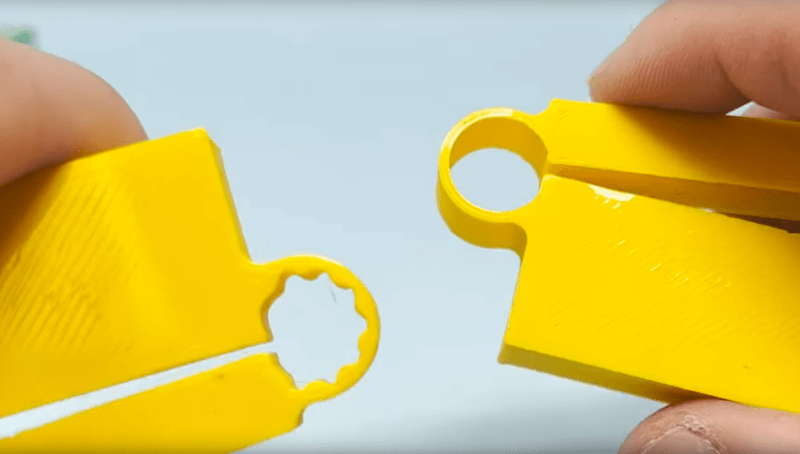
The first note is to make sure that you’re using the right kind of plastic, but after that’s taken care of [Slant 3D] builds a few flexible parts starting with longer circular-shaped living hinge which allows greater range of motion and distributes the forces across a wider area, at a cost of greater used space and increased complexity. A few other types of living hinges are shown to use less space in some areas, but make the hinges only suitable for use in other narrower applications.
One of the more interesting living hinges he demonstrates is one that’s more commonly seen in woodworking, known there as a kerf bend. By removing strips of material from a sheet, the entire sheet can be rotated around the cuts. In woodworking this is often done by subtracting material with a CNC machine or a laser cutter, but in 3D printing the voids can simply be designed into the part.


It’s a nice overview, some remarks:
The toothed look (@01:57) does not work at all. The only thing it does is remove the “thicker parts” from the hinge parts. that it seems more flexible is because the thin parts are made thinner. This way is also known as a “flexure”, and the ideal shape of a flexure is that stresses are divided evenly, This does not mean it has to have the same thickness overall. A flexure is often also a lever, and the force in a lever changes with the distance from the fixed point. There is plenty of material to study flexure design.
In general, you also want to avoid sharp corners in flexures such as shown @00:26.
Another excellent example of a flexure in steel is the Repeat-o-Meter from Robrenz I find it quite astonishing he has only 53k subscribers on youtube. I guess his video’s are “too technical” for most folks.
The “Gripper Finger” (@02:23) reminds me of the Festo “Adaptive gripper fingers”. That is an excellent example of a well designed complex flexure.
Where 3d prints are concerned the toothed look is probably a very good idea sometimes.
The layers don’t stick to each other nearly as well as the rest of the plastic in the x-y plane so those teeth give you more layer to layer bond area while still getting the very thin spots for it to flex well. Not saying you are wrong in general but 3d printing is rather odd beast that doesn’t entirely follow the expected behaviours of the materials you printed in, and some materials are much harder to get good layer to layer adhesion than others – which is where that toothed idea is likely the ideal compromise.
Of course what is actually best will vary hugely on material and printer. You probably can’t print that 0.2mm type flexure positions that you could water/laser out of the same material regardless, as good as 3d prints are they still are not really solid. And if you have a nozzle capable of putting out the entire flex part in one single extrusion then maybe you can more easily get away with the potential for poor layer adhesion across that flexure with it being well anchored into the rest of the part and more solid in its own right. Also thicker individual extrusions tend to bond layer to layer to better anyway…
The literature indicates that PLA does have an elastic region in its stress/strain graph, so if you can keep the strain down in the linear elastic deformation region, it shouldn’t wear out. This doesn’t take into account either creep (which you could deal with by making the flexure in its relaxed state, if the design allows for that) or fatigue. The papers I’ve read indicate that there may be a fatigue limit of about 10% of the yield strength, so it’s possible that with careful design, even that may be largely avoidable.
Two points:
1 throw away all the assumptions about what PLA is and how it’s different from “sturdier” plastics for FDM. The number of types of materials available in 2023 is astounding. You can get PLA that’s tougher and more flexible than the nonPLA stuff that’s problematic to print.
2 I have searched high and low for a necronomicon model with a living hinge but I may have to conjure one of my own.
Plastic hinges eventually crack, involving design for failure. Since a hinge is intended to flex, consider another strategic material phased into the print fir the hinge.