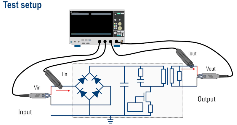
Even if you don’t have a Rohde Schwarz oscilloscope, you can still enjoy their recent video about using an oscilloscope to measure power supply efficiency. Of course, you don’t have to have a scope to do this. You can use a voltmeter and an ammeter, but it is very straightforward if you have a four-channel scope with a pair of current probes.
Of course, if you can measure the voltage and the current at the input, you can calculate the input power. Then again, most scopes these days can do the math for you. Then, you make the same measurement and calculation at the output. If you know the input and output power, you can calculate a percentage or many scopes can do it for you now.
The video reminds you that modern power supplies are often very efficient, so you want precise measurements. Depending on your equipment’s capabilities, you might do better measuring the current with a precision meter or using a sense resistor in series and measuring the voltage, although, obviously, a current probe will be more convenient.
Of course, if you only have a two-channel scope, you could do the measurements sequentially, assuming the power supply is in a steady state or close to it. You could also do the measurement with one or more multimeters. After all, multimeters are pretty cheap, so dedicating four of them to this task wouldn’t be that prohibitive.
Current probes tend to be expensive, but there are relatively low-priced ones out there. Good current probes use Rogowski coils, a topic we’ve talked about before.


“Of course, if you can measure the voltage and the current at the input, you can calculate the input power.”
You cannot do so unless your power supply has power factor control. Mostly you have a phase shift between voltage and current and you have to measure the power factor. This can be done on a scope. When you have a non-sinusiodal current which is normally the case you can’t do it this way at all. So forget about the multimeters for AC power measurements.
I would assume the Rohde & Schwarz scope has isolated channels or differential probes are being used to measure the voltages.
Otherwise in a real world power supply you will be probably let out the magic smoke by shorting the Vin AC supply and the bridge rectifier to ground through the scope probe ground or alternatively short the input AC to Vout AC via the other probe ground.
They do mention differential probes, though they don’t spell out why you would need them. This seems strange as the video appears to be aimed at those without a lot of electonics experience. Also how many people not familiar with the concepts of a power supply are going to have access to a Rohdes & Swartz scope? They’re not really entry level.
Yeah, and differential probes are not that cheap either. For beginners, a couple of dollar store multimeters will be easier and more accurate, at least for DC usage. Entry level scopes have usually about +- 3% accuracy spec.
There are many videos on their channel. They have one on differential probes.
https://www.google.com/search?sca_esv=4a9f74e1b740eb2c&sxsrf=ACQVn09bFhZEP0KENy41SJBA8aw5IFm0_w:1707510618145&q=rohde+schwarz+differential+probe&tbm=vid&source=lnms&sa=X&ved=2ahUKEwjky-DejJ-EAxXzywIHHftwAmgQ0pQJegQIDBAB&biw=1615&bih=795&dpr=1#fpstate=ive&vld=cid:dc94c5a3,vid:WHWMbGcCppo,st:0
“Good current probes use Rogowski coils, …”
Ahem, no, they don’t.
+1
Just a reminder to folks measuring power that avg(P) = avg(v*i) != avg(v)*avg(i).
That is, you need to take the voltage and current waveforms and multiply them point by point before taking the average to get average power.
If you take the average of the voltage and multiply it by the average of the current, you will get a number that looks like watts, but it will not be the average power consumption.
I see this mistake made often, even by experienced engineers.
If you really want to measure the power loss accurately, you should use a calorimetric method.
I chuckle at the thought of a power supply running in a bomb calorimeter, but you’re right, that probably is the best way.
FWIW I do this a lot at work and we can easily get below the tolerance of most of the parts in the system using 0.1% current sense resistors. Like, if your inductor is 10% and most of your caps are 5%, while you can do a really good job measuring efficiency on a single unit, if you are characterizing several dozen units there’s not a lot of point in pursuing either accuracy or precision more than like 10x better than your worst tolerance part. (Depending on how much effect it has, which is an error propagation exercise.)
The inductor (10 % ?) or caps don’t have a direct or predictable effect on efficiency; likely a 10 % change in the inductance will have a completely undetectable change in efficiency.
Conversely, you don’t need 0.1 % sense resistors — as long as you use the same R on the input and output, any resistance variation will cancel out in the efficiency measurement. For higher current supplies, you do need a resistor with a low thermal coefficient.