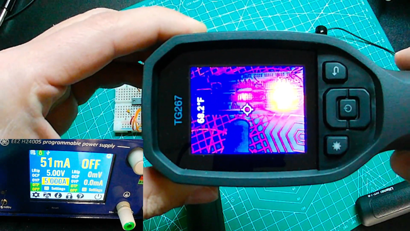
[Dr. Shane] asks the question: what happens if you connect the output of an inverter logic gate back to the input? In theory, it doesn’t make sense, but depending on the gate’s physical construction, you’ll get into a strange state. The transistors within the gate will behave differently than they normally would, and you’ll wind up with an amplifier or an oscillator. You can see the results in the video below. In the second video, you can see what the odd connection does to the thermal properties of the inverter, too.
The CMOS inverter becomes biased in the active region, so it makes sense that it settles at the halfway point. The TTL inverter is slightly different, but the delay through the gate isn’t enough to produce a good oscillation. However, an odd number of inverters connected in a ring like this is one way to create a simple oscillator.
While we don’t suggest this method, it is interesting to see what happens when you bias different gates this way. We’ve certainly seen it done using a variety of different inverter types ranging from discrete transistor circuits to inverters on the die of an IC.
We’ve seen ring oscillators in a number of forms. Inverters can also make the phase-shifting part of a crystal oscillator.


When you connect an inverter that way Michael J Fox’s siblings start to disappear from pictures.
If the inverter has schmitt-trigger inputs, then it will almost always make an oscillator because the rise time of the output will be limited, the internal circuit has some propagation delay, and the input has hysteresis, so it bounces back and forth between the two states.
Also, building the circuit on a breadboard adds capacitance and inductance, so that may load up the circuit enough that it kills the oscillation before it can start.
I get about 4pf between lanes on all my breadboards, that is not much more than the internal capacitance between two pins on a DIP IC. Sure – there are cases where an additional 4pf will be bad, but for a bog standard LS/HC design it generally won’t be a problem. People always lament about the issues of breadboard, especially the “horrible” capacitances all over the place. I’d say that bad connections on low quality breadboard are more of an issue.
Of course, in a single gate oscillator as in this post the additional capacitance of the breadboard would have some effect ;-)
I’ve usually measured between 3-10 pF.
The gate capacitance of a tiny FET may be in the femtofarads, so a million times smaller than the external capacitance on the breadboard. The gate wants to oscillate, but at a much higher frequency than the feedback circuit on the breadboard would allow, because the signal at the gate’s “natural frequency” simply bleeds to ground and dies off.
You can deliberately add impedance to the feedback path though and cause a phase shift that will make the gate oscillate, sometimes.
Sorry, 1000 times smaller. I got pico and femto the wrong way around.
> but the delay through the gate isn’t enough to produce a good oscillation.
See:
https://en.wikipedia.org/wiki/Barkhausen_stability_criterion
The phase shift through the NOT gate is 180 degrees, which creates negative feedback and steers the circuit towards the middle. The input impedance of the gate is essentially an RC low-pass filter that can add no more than 90 degrees more shift, up to 270 degrees, at which the portions of positive and negative feedback are essentially 50:50. With a loop gain of less than 1 (no voltage amplification in between) this cannot start oscillation. It may wobble a bit, but eventually settles down.
If you slow it down with yet another low-pass filter for another 90 degrees, you approach 360 degrees of phase shift and that creates more POSITIVE feedback instead of negative feedback that would steer the output towards the middle. The system can now start oscillating with a loop gain of less than 1 – though it’s difficult to make one that actually starts.
Example:
https://i.stack.imgur.com/WeLaE.png
Two NOT gates with the gate delays pushes the system past 360 degrees of phase shift, and away from positive feedback and oscillation. In the ideal case it can only oscillate at zero frequency – but it’s not stable. It will pick either one or zero and stay there, which is actually the basis for static RAM:
https://moodle.insa-toulouse.fr/file.php/58/content/static_ram.html
With three NOT gates you get 360 + 180 degrees out of the gates, plus the gate delays that depend on the frequency, so you get back towards the situation with an oscillation point at some frequency where the gate delays add up to another 180 degrees of phase shift and the feedback can become positive again. This is the three (or any odd number) inverter ring oscillator.
Or, that’s at least what I understood of the theory.
reminds me of a circuit I built once out of a magazine when I was too poor/cheap to just go down to Radio Shack and buy a proper RF Modulator for my Apple ][e clone. It worked, but just barely.
I’ve used 74HCU04 hex inverters, (the ‘U’ sands for un-buffered), as RF amplifiers. A resistor between output and input biases the output at about one-half the supply voltage, and turns the ‘digital’ device into a linear amp. I even put one such design into production. We’re talking relatively low frequencies – around 14 MHz, although if I remember correctly I had one working at 24MHz.
They worked well – linearity wasn’t great, but I had good passive filtering on the output so it didn’t matter. From the standpoint of simplicity, parts count, and cost, they were unbeatable. Sections of the chip can even be paralleled for lower output impedance. I wouldn’t want to use the separate buffers in one for different signals though, at least not at those frequencies…
An odd number of CMOS inverters in series (three is a good number) with something like 10 meg wrapped around for feedback, and maybe a 220 k series resistor on the input, makes a pretty decent audio amp.
See
“Simple Circuit Yields High Frequency Clock and Propagation Delay Check”,
The Electronic Engineer, Vol. 27, No. 8,
in which the author uses a hex-inverter package to create a high(er) frequency oscillator (three inverters), or a lower frequency one using five inverters. One inverter is (wisely) reserved for use as an output buffer.
I wonder what happens, if you put the plug of an extension cord into one of the sockets of that same extension cord… and would it matter if you flip the plug 180 degrees.
Congrats! You might have invented the Möbius power strip.
That’s both twisted and loopy at the same time
“would it matter if you flip the plug 180 degrees.”
If you powered it, yes… it would most definitely matter if you did that ;-)
Schmitt trigger Cmos inverters connected with a resistor this way, MUST Oscillate. They can’t do anything else! Put a timing network on the input, ie a capacitor, and you can lower the frequency, and they make good, simple oscillators. An R, C & one schmitt inverter! If you put a crystal, eg 32KHz watch crystal, with about 2MOhm feedback resistor and the oscillator will lock to the resonant crystal frequency.
Not necessarily. It should, but with non-ideal components doing weird things (e.g. a wire wound high value resistor having inductance as well), it may not start.
Here’s how the kids did it in the olden days of the Cray 1S.
https://youtu.be/jNqLdsqO5_c?si=c_rpsd29s-pnwyu-&t=380
HEY! Oscillating inverters to generate the master clock in a supercomputer!
This was ECL stuff, so all the TTL and CMOS explanations above will partly apply and partly not.