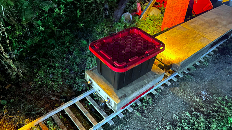
There’s something magical about a train, whether you call it a railway or a railroad, plenty of us have hankered after our own little piece of line on which to shunt wagons or chuff around our domain. Envy [Otis Rowell] then, because he’s made himself a garden railway with the laudable purpose of moving wood pellets for his heating. A mere garden railway may be cool but it’s not in itself special, so the reason we’re featuring it here comes from something else. He’s making his rail wheels by 3D printing them with a normal printer.
It’s important to understand that these wheels are not for a high-speed mainline express freight train but for a small flat car designed to carry a modest tub of pellets, thus they are less in need of high strength than their full-size cousins. But even a small car on garden railway-sized aluminum rails can exert significant force, so we would be fascinated to see how well these do. The write-up is a work in progress as this article is being written so we know there’s more to come, but there’s no harm in speculating as to how a better 3D-printed wheel might be made. We would be particularly curious for example as to whether a novel slicing regime could be used to make a stronger wheel.
If backyard railways interest you, it’s not the first time we’ve seen one.


“A mere garden railway may be cool but its not in itself special, so the reason we’re featuring it here comes from something else”
Don’t gatekeep the trains. More custom trains plz.
Not into model trains myself but this is a great project, I wonder which areas may get attention, durability seems like one but is durability offset by the fact that you can print these in short order + cost less than $200 for a bogie a bigger factor?
What about different filament types for durability too?
Just print them in POM? Assuming you have a decent printer
Wear part?
Rails or wheels?
Best to think it through. Aluminum rails at that scale can’t be cheap.
Real world rails are hardened on the bearing surfaces.
Wheels cost a shitload, but routine machining. Less than new rails. Bearings need attention anyhow.
Then again, will it see significant use and abuse?
Is it just a matter of time before destructive overload testing by teenagers playing jackass? Avoid contact with lawyers.
Just how ingenius is the idiot it must be protected from (drunken builder on a bad day).
Also: Where pulsejet mount?
This could have a pulsejet, therefor it should have a pulsejet.
Obviously, the 3d printed wheels will be the wear part, but I looked at project.
He’s considering better wheels. Better than his track.
Dual pulsejets.
Thanks for the write-up! And, yes, very much a work-in-progress! I’m hoping to have the next build log written shortly, but the wheels are definitely the wear part. (And also have serious problems with any sort of bend ATM, causing the flange to rip off on the rev5 wheel parts)
I didn’t think about the alternate slicing options, definitely something to consider for rev10.
the bend will be what the bogie is for I guess?
Normally, yes, I just didn’t take account for the “Extra Distance” needed when building the curve. I had set the entire section of track to a consistent 13 inch gauge, ignoring potential curve issues. (Also had way too tight of a curve)
Island Pond RR, another garden gauge railroad has a good tool for computing extra distance on a curve, I hadn’t stumbled upon it until later.
https://gardei.com/IPRR/radius.htm
Train wheels are tricky.
It appears you have no taper on your flats. (Pics ain’t great.)
Also, radius all those corners. Especially the one between flat and flange. Sharp corners bad, concentrate stress.
Banking the turns will make the thing much more fun for the neighborhood kids who play ‘roller coaster’ on it.
There’s a very minor taper on the flats, (yeah pics aren’t great) but only about 1mm. The wheel has been an evolving model over the past 4-5 years, and I’ll try to smooth out the corners on the next model revision. Thanks for the pointer
It pays on the long run to use standard values as much as possible, so you can later use parts you get from elsewhere. For the wheels profile I would start somewhere near the standard rail profile (https://de.wikipedia.org/wiki/%C3%84quivalente_Konizit%C3%A4t?useskin=vector seems to lack an english version, but has nice pictures). The wheel is the wear part, because it hits the contact point once per round, while the track hits it only once per axle.
Disclaimer: the optimization of the wheel-track-interaction is a serious rabbit hole to dive into.
Why not use the 3d printed parts for sand casting? He could make the wheels from aluminum. They last long and pretty cheap to make if you know how.
That’s definitely something I’ll consider in the next few years. At the moment, I’m kinda curious to see how far I can get with 3D printing different materials and different slicing options
Great project, Otis Rowell. I hope your rail system lasts many years.
Remind’s me of Max Maker’s train for his trash bins
https://www.youtube.com/watch?v=VhYEOG9LOIk