If you’ve ever been laying out a network I2C devices inside a project box or throughout your robot’s body, you’ll probably know that I2C is not without its pitfalls. But for many of those pitfalls, there’s a handy chip you can use. [Roman Dvořák] from ThunderFly has experienced it on their drone building journeys, and that’s why they bring us two wonderful open source hardware boards: an I2C bus extender, and an I2C address translator.
The first board, an I2C bus extender, is based around the TCA4307 chip, and not only it lets you extend the bus further than it would normally go, it would also protect you. When the bus capacity is no longer handleable by your devices, or a particular misbehaving device gets the bus stuck, this chip will take care of it and dissipate your troubles. It will even let you know when your bus is wired up correctly, with a handy shine-through LED!
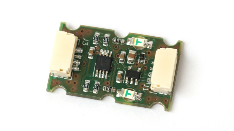
The second board is an I2C address translator. We’ve covered them before, but in short, address translators let you avoid I2C address conflicts while using multiple devices that share the same address. This particular module uses the LTC4317 chip, a common choice for such translation, and the board leaves no feature unimplemented. In the README, there’s quite a few pictures with examples of where this sensor proves mighty useful, too!
It appears that ThunderFly open sources a lot of their designs on GitHub, an effort that we salute. The designs are great to learn from, but if you’re just looking for turn-key hardware, you can get both of these boards from their Tindie store. The cables they use have locking connectors, but as long as the pinout matches, you should be able to solder a JST-SH socket and add these modules to your QWIIC toolkit.


“but as long as the pinout matches, you should be able to solder a JST-SH”. Unfortunatley not, I just checked and they’re different series and so have a different pitch. They also have different pinouts.
Side note, sparkfun make it surprisingly difficult to reference the pinout for the qwiic system without a little digging. I found one pdf for the cables which showed pin number to colour, and another that showed the relationship between wire colours and function. If anyone at sparkfun happens across this could we please have a doc that unifies these?
Link in this article: https://hackaday.com/2022/05/04/the-connector-zoo-i2c-ecosystems/
GND and VCC are easy to guess. Other two go in order?
Thanks, I’d completley forgotten about that article, though I definitley read it at the time.
From the schematic in the ThunderFly github repo they’re using the following pinout…
1/ +5V
2/ SCL
3/ SDA
4/ GND
If the pinout is that then its not QWIIC.
Finding the QWIIC pinout isn’t difficult though? Search for “sparkfun qwiic pinout” and the Sparkfun QWIIC page is the first result. The FAQ section has the pinout and connector part numbers.
I thought it was like a translator to SPI or something lol