If you want to start an argument at a Hackaday meeting, you have only to ask something like “How much does this weigh?” or “What time is it?” But if you really want to start a street brawl, you can always say, “Are these numbers random?” Making random numbers that are actually random is actually a tough nut to crack. Most of what we do is, technically, pseudo-random (but we’ll say random number and assume you know what we mean). One way to generate seemingly random sequences is to use a linear feedback shift register or LFSR. You can use LFSRs in software, but they are also very useful in hardware design and [Adam Taylor] takes us through his use of them on FPGAs in a recent post.
As [Adam] points out, they not only generate random-like patterns but they are often used as high-performance counters and in error detection and correction schemes. As the name implies, the mechanism is a simple shift register with one or more of its outputs fed back around to the input. How can that be random? Well, it can’t be, but it is often good enough for places where you need a sequence of numbers. Depending on how you organize the outputs — or taps — and how you feed them back means you can control the pseudo-random sequence.
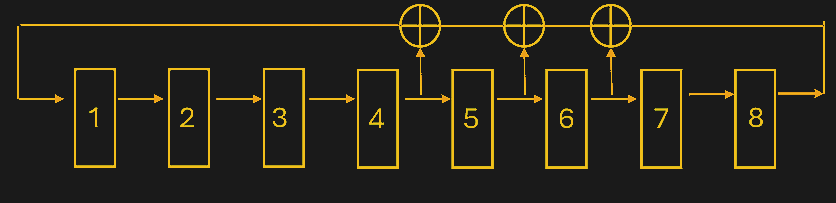
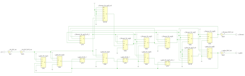
There are two common methods for creating LFSRs. A Fibonacci-style design uses XOR (or inverted XOR) gates in the feedback loop. For example, consider an eight-stage counter. The post shows the output of flip flop 4, feeding an XOR gate that drives the counter’s input. The other input of the XOR gate is the output of another XOR gate that receives input from flip flop 5 and the output of yet another XOR gate. That XOR gate receives its inputs from flip flop 6 and the output of the shift register.
The Galois scheme is similar, but uses the XOR gates in the shift path. In other words, the output of the shift register directly feeds the input, but it also feeds several XOR gates that go between the flip flops. Why choose one over the other? Read the post. The summary is that it depends on how your FPGA resets and what kind of support it has for shift registers so, as usual, it pays to understand what’s going on in the FPGA fabric.
As for where to put the taps, it depends on how you want the pattern to repeat. If you want the repeating kept to a minimum, you can look them up in a table based on research from [Wayne Stahnke] and popularized by Xilinx in an app note. [Solomon Golumb] also published tables of taps for maximum sequence generation. As you might expect, there’s a program that will help you if you don’t want to use the tables.
The math may be hairy, but implementing this in hardware is simple if you ever need a random-looking sequence. Maybe you want a random flicker in your fake candle. You can do it with relays, even.


Given a deterministic universe, there is no random. Only seemingly random due to our lack of understanding.
>Given a deterministic universe
Evidence for this? Given the cause-effect relationship that isndeterminism, what was the first cause?
You think we live in a deterministic universe? I recommend you upgrade your textbooks from Newtonian physics to quantum mechanics. In particular, take note of Schrödinger and Heisenberg. Our lack of understanding is often rooted in the randomness of the Universe and only improves when we take randomness into account. As to our topic in the article, consider https://en.wikipedia.org/wiki/Quantum_random_circuits
Quantum mechanics is entirely deterministic and even linear. That is the evolution of the wave function is determiniatic and linear.
It’s just the so called collapse of the wave function that random, but that’s not part of quantum mechanics, only part of some interpretations of it, like the old Copenhagen interpretation. Many-worlds doesn’t have wave function collapse, neither random nor otherwise.
(Of course, you still have the Born rule.)
“if you pretend that everything possible happens, it’s deterministic!” Is… a choice, I guess
Looks like you’re stuck at Newton buddy. Total determinism has been dead for a long while
Since the ’80s I’ve had in my mind the possibility of a processor with a pseudo-random program counter! The idea being that a linear feedback shift register uses fewer gates than a full adder/incrementer, but with suitable tap points would generate a maximal length sequence for the PC size. But these days gates are plentiful so probably yet another never-do-it project!
The Intel 8008 used a nonlinear feedback shift register for the stack counter.
http://www.righto.com/2017/03/analyzing-vintage-8008-processor-from.html
Thank you; according to the notes at the end there the TMS1000 had pseudo-random program counter, so TI beat me to it by 50 years!
LFSR counters got used for address-type counters a lot in days of yore: it’s not just that it’s fewer gates, it’s fewer gates in the critical path.
You still do get some savings in FPGAs because of the limited feedback logic – in most FPGAs ripple-carry adders require 1 LUT/bit and need to pack tightly no matter what because they have to use the carry chain, whereas an LFSR can mostly use registers only and frees up the routing.
Coded an LFSR into a PIC 12F675 years ago.
Added a power transistor and used it to run a short string of LED Christmas lights.
Drove my mother crazy trying to work out the pattern.
Job done.
What happened to rhe dude that told HP their calc Rnd fn wasnt?
Rather than “random” I’ll settle for “chaotic”.
The longer you need to observe the output, in order to determine the sequence (or your place in a known sequence) the more chaotic the system is.
Or, you know. Use the correct term: pseudorandom. Chaotic means something different.
The Xilinx app note makes a few weird choices for some LFSRs. There are also a class of LFSRs that can be implemented in the built in shift registers, making them absurdly tiny.
Because they’re deterministic sequences you can use them for large delays instead of counters: it’s cheaper to detect a run of n equal values (log2(n)) plus an LFSR if the LFSR only costs you a LUT+FF or two.
https://github.com/barawn/verilog-library-barawn/wiki/Timer-clock-enable-divider-tricks#lfsr-timer
I think the term pseudorandom is most appropriate. LFSR have periodicity so def not truly random.
Did you, uh, read the article?
I immediately read this. Implemented keeloq decoding and encoding for the Yardstick One for RF rx and tx. Keeloq is a Non Linear Feedback Shift Register.
Hi, thank you for posting it. Let me clear the idea of randomness. There are 2 classes of randomness, true random and pseudo random. They both exhibit random patterns, the only difference is the probability dependency. True random is truly unpredictable, and only achievable in hardware. Pseudo random has equal chance for all number, can be done on software and hardware. Says if the first sequence is 1 (or seed), then we know that the next sequence will have higher chance, much like card counting. The LFSR random patterns will repeat for every complete shift cycle.
For those says that LFSR is useless, FYI, I implemented AI CNN hardware accelerator on FPGA with LFSR as the clock source, literally. There are more exotic computing paradigms than you could imagine. Read more literature before leaving comment. Anyway, it is a good start to explore randomness in FPGA, keep the good work.
I happen to love cryptographically weak prng. The NES/Famicom made good use of LFSR in games. An encoded drum pattern can be put through an LFSR to give you a whole sequence of pattern permutations. And all of this at very minimal system resources, or can be done without a CPU even with logic circuits.
“For those says that LFSR is useless”
I would say that there’s very few people reading this for which the statement wasn’t encoded and decoded through an LFSR, considering they’re the basis for whitening in PCIe/USB3/GigE/SATA/HDMI/etc.
Did y’all not read the damn article? The word “pseudo-random” occurs within the first 4 sentences.
That’s how the Atari vcs graphics chip was built
Using a bunch of lfsr organized in polynomial counting logic
Explain why the 2600 has the most unique audio tones, since its frequency is tapped (divided) from different stages of an oscillator/lfsr circuit but I guess Jay miner didn’t have the most musical ear
Guess he learned by the time the pokey came into being or just had someone else do it.
Why Atari punk console is simple to build…
Even with just a 555
“gfsr pseudo random number generator”
https://www.google.com/search?q=gfsr+pseudo+random+number+generator&rlz=1C1QCTP_enUS1084US1084&oq=gfsr+psuedo+random&gs_lcrp=EgZjaHJvbWUqCQgBECEYChigATIGCAAQRRg5MgkIARAhGAoYoAEyCQgCECEYChigATIJCAMQIRgKGKAB0gEJMTk3ODRqMGo3qAIIsAIB&sourceid=chrome&ie=UTF-8
FPGAs a good platforms for implementation?
The gfsr can have longer cycle length than there are atoms in the universe, first author Ted G Lewis told me.
https://www.google.com/search?q=ted+g+lewis+compulter+bio&rlz=1C1QCTP_enUS1084US1084&oq=ted++g+lewis+compulter+bio&gs_lcrp=EgZjaHJvbWUyBggAEEUYOTIJCAEQIRgKGKABMgkIAhAhGAoYoAEyCQgDECEYChigAdIBCTI3NDM5ajBqN6gCCLACAQ&sourceid=chrome&ie=UTF-8
I have not investigated.
Busy on other stuff.
Cycle length isn’t a meaningful metric to compare algorithms. Anything can have a cycle length that long (a several-hundred bit LFSR would, for instance), and nothing algorithmic can have a cycle length longer than 2^(total number of bits). LFSRs are actually very efficient in terms of cycle length per generated bits given that they only give up one state.
https://hackaday.io/project/178998-peac-pisano-with-end-around-carry-algorithm
can beat LFSR in certain cases yet remain very simple.