If you want to start an argument at a Hackaday meeting, you have only to ask something like “How much does this weigh?” or “What time is it?” But if you really want to start a street brawl, you can always say, “Are these numbers random?” Making random numbers that are actually random is actually a tough nut to crack. Most of what we do is, technically, pseudo-random (but we’ll say random number and assume you know what we mean). One way to generate seemingly random sequences is to use a linear feedback shift register or LFSR. You can use LFSRs in software, but they are also very useful in hardware design and [Adam Taylor] takes us through his use of them on FPGAs in a recent post. Continue reading “Linear Feedback Shift Registers For FPGAs”→
[Wenting Zhang] is clearly a fan of old school STN LCD displays, and was wondering how various older portable devices managed to drive monochrome LCDs panels with multiple grey levels. If the display controller supports multiple bits per pixel, it can use various techniques, such as PWM, in order to produce a pseudo-grayscale image. But, what if you have a monochrome-only display controller? With a sufficiently high pixel clock, can you use software on the application side of things to flip those pixels in such a manner as to give a reasonable looking grayscale image?
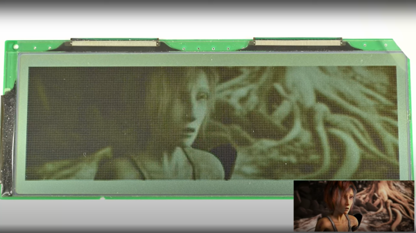
Simple dithering – don’t look too close!PDM greyscale approximation in a 1-bit display
[Wenting] goes through multiple techniques, showing the resulting image quality in a clear, systematic manner. The first idea is to use a traditional dithering technique. For each pixel, it is set to black if the grey value is below some threshold. The resulting error value, is then propagated to neighbouring pixels. This error diffusion process smears the error out over the whole display, so spatially speaking, on average the pixel values correspond roughly to the original gray values. But, the pixels themselves are still either on or off. This isn’t quite enough. The next idea is to PWM the individual pixels over multiple frames, to approximate different grey levels. But, that gives a worst case effective refresh rate of 8 Hz with a PWM period of 15 frames, at 120 fps, and that flickers. Badly. One way to mitigate that is to switch to PDM (pulse density modulation) which selects different length sequences to give the same duty cycle but at higher frequency, at least for some grey values. Slightly better, but there’s more that can be done. Continue reading “Monochrome LCD Video Hacks Galore!”→
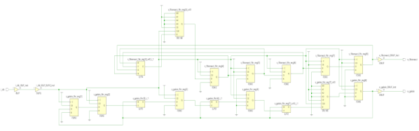
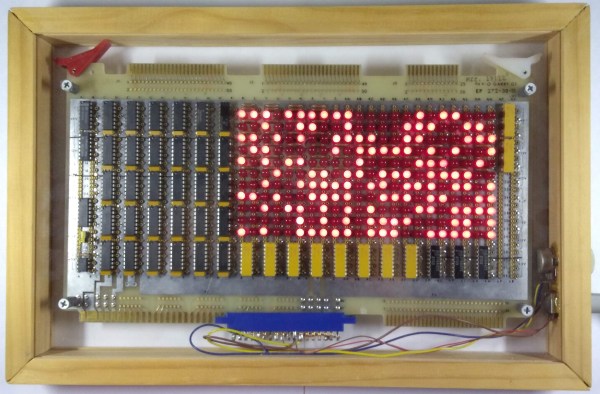
The core of the project is a 242-bit linear-feedback shift register (LFSR) constructed from (31) 74LS164’s. An XOR gate and inverter computes the next bit of the sequence by XNOR’ing two feedback bits taken from taps on the register, and this bit is then fed into bit zero. Depending on which feedback taps are chosen, the output sequence will repeat after some number of clock cycles, with special sets of feedback taps giving maximal lengths of 2N – 1, where N is the register length. We’ll just note here that 2242 is a BIG number.
The output of the LFSR is displayed on a 22×11 array of LEDs, with the resulting patterns reminiscent of retro supercomputers both real and fictional, such as the WOPR from the movie “War Games,” or the CM2 from Thinking Machines.
The clock for this massive shift register comes from – wait for it – a 555 timer. A potentiometer allows adjustment of the clock frequency from 0.5 to 20 Hz, and some extra gates from the XOR and inverter ICs serve as clock distribution buffers.
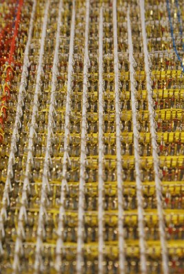
We especially love the construction on this one. Each connection is meticulously wire-wrapped point-to-point on the back of the board, a relic originally intended for an Intel SBC 80/10 system. This type of board comes with integrated DIP sockets on the front and wire-wrap pins on the back, making connections very convenient. That’s right, not a drop of solder was used on the board.
You can see 11 seconds of the pattern in the video after the break. We’re glad [Quinn] didn’t film the entire sequence, which would have taken some 22,410,541,156,499,040,202,730,815,585,272,939,064,275,544, 100,401,052,233,911,798,596 years (assuming a 5 Hz clock and using taps on bits 241 and 171 ).