If you need a precise time, you could use a microcontroller. Of course, then all your friends will say “Could have done that with a 555!” But the 555 isn’t magic — it uses a capacitor and a comparator in different configurations to work. Want to understand what’s going on inside? [Mano Arrostita] has a video about simulating delay and timer circuits in LTSpice.
The video isn’t specifically about the 555, but it does show how the basic circuits inside a timer chip work. The idea is simple: a capacitor will charge through a resistor with an exponential curve. If you prefer, you can charge with a constant current source and get a nice linear charge.
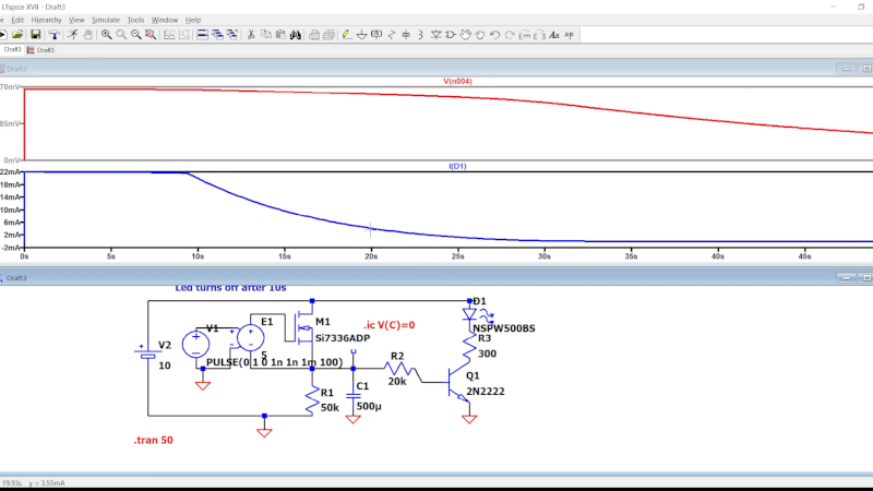
You can watch the voltage as the capacitor charges and when it reaches a certain point, you know a certain amount of time has passed. The discharge works the same way, of course.
We like examining circuits for learning with a simulator, either LTSpice or something like Falstad. It is easier than breadboarding and encourages making changes that would be more difficult on a real breadboard. If you want a refresher on LTSpice or current sources, you can kill two birds with one stone.


Oscillators take a bit of coaxing to get to working in LTSpice. Usually it involves setting the initial voltage of a node as 0V or skipping initial operating point evaluation
Could have used a ‘555.