Delays And Timers In LTSpice (no 555)

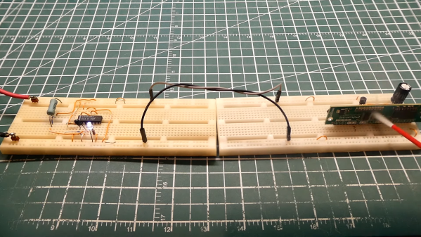
If you need a precise time, you could use a microcontroller. Of course, then all your friends will say “Could have done that with a 555!” But the 555 isn’t magic — it uses a capacitor and a comparator in different configurations to work. Want to understand what’s going on inside? [Mano Arrostita] has a video about simulating delay and timer circuits in LTSpice.

The video isn’t specifically about the 555, but it does show how the basic circuits inside a timer chip work. The idea is simple: a capacitor will charge through a resistor with an exponential curve. If you prefer, you can charge with a constant current source and get a nice linear charge.

You can watch the voltage as the capacitor charges and when it reaches a certain point, you know a certain amount of time has passed. The discharge works the same way, of course.

We like examining circuits for learning with a simulator, either LTSpice or something like Falstad. It is easier than breadboarding and encourages making changes that would be more difficult on a real breadboard. If you want a refresher on LTSpice or current sources, you can kill two birds with one stone.

Continue reading “Delays And Timers In LTSpice (no 555)”

Back To Basics With A 555 Deep Dive

Many of us could sit down at the bench and whip up a 555 circuit from memory. It’s really not that hard, which is a bit strange considering how flexible the ubiquitous chip is, and how many ways it can be wired up. But when was the last time you sat down and really thought about what goes on inside that little fleck of silicon?

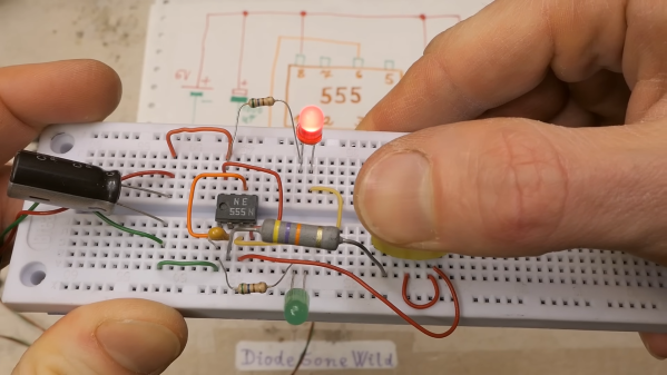
If it’s been a while, then [DiodeGoneWild]’s back-to-basics exploration of the 555 is worth a look. At first glance, this is just a quick blinkenlights build, which is completely the point of the exercise. By focusing on the simplest 555 circuits, [Diode] can show just what each pin on the chip does, using an outsized schematic that reflects exactly what’s going on with the breadboarded circuit. Most of the demos use the timer chip in free-running mode, but circuits using bistable and monostable modes sneak in at the end too.

Yes, this is basic stuff, but there’s a lot of value in looking at things like this with a fresh set of eyes. We’re impressed by [DiodeGoneWild]’s presentation; while most 555 tutorials focus on component selection and which pins to connect to what, this one takes the time to tell you why each component makes sense, and how the values affect the final result.

Curious about how the 555 came about? We’ve got the inside scoop on that.

Continue reading “Back To Basics With A 555 Deep Dive”

Simple CMOS Circuit Allows Power And Data Over Twisted-Pair Wiring

If you need to send data from sensors, there are plenty of options, including a bewildering selection of wireless methods. Trouble is, most of those protocols require a substantial stack of technology to make them work, and things aren’t much easier with wired sensors either. It doesn’t have to be that complicated, though, as this simple two-wire power-and-data interface demonstrates.

As with all things electronic, there are tradeoffs, which [0033mer] addresses in some detail in the video below. The basic setup for his use case is a PIC-based sensor — temperature, for this demo — that would be mounted in some remote location. The microcontroller needs to be powered, of course, and also needs to send a signal back to a central point to indicate whether the monitored location is within temperature specs. Both needs are accommodated by a single pair of wires and a tiny bit of additional circuitry. On one end of the twisted pair is a power supply and decoder circuit, which sends 9 volts up the line to power the PIC sensor. The decoder is based on a CD4538 dual monostable multivibrator, set up for an “on” time of one second. A trigger input is connected to the power side of the twisted pair going to the sensor, where a transistor connected to one of the PIC’s GPIO pins is set up to short the twisted pair together every half-second. Power to the PIC is maintained by a big electrolytic and a diode, to prevent back-feeding the controller. The steady 0.5-Hz stream of pulses from the sensor keeps resetting the timer on the control side. Once that stream stops, either through code or by an open or short condition on the twisted pair, the controller triggers an output to go high.

It’s a pretty clever system with very simple and flexible circuitry. [0033mer] says he’s used this over twisted-pair wires a couple of hundred feet long, which is pretty impressive. It’s limited to one bit of bandwidth, of course, but that might just be enough for the job. If it’s not, you might want to check out our primer on current-loop sensors, which are better suited for analog sensors but still share some of the fault-detection features.

Continue reading “Simple CMOS Circuit Allows Power And Data Over Twisted-Pair Wiring”

Clock Escapement Uses Rolling Balls

The escapement mechanism has been widely used for centuries in mechanical clocks. It is the mechanism by which a clock controls the release of stored energy, allowing it to advance in small, precise intervals. Not all mechanical clocks contain escapements, but it is the most common method for performing this function, usually hidden away in the clock’s internals. To some clockmakers, this is a shame, as the escapement can be an elegant and mesmerizing piece of machinery, so [Brett] brought his rolling ball escapement to the exterior of this custom clock.

The clock functions as a kitchen timer, adjustable in 10-second increments and with several preset times available. The rolling ball takes about five seconds to traverse a slightly inclined, windy path near the base of the clock, and when it reaches one side, the clock inverts the path, and the ball rolls back to its starting place in another five seconds. The original designs for this type of escapement use a weight and string similar to a traditional escapement in a normal clock. However, [Brett] has replaced that with an Arduino-controlled stepper motor. A numerical display at the bottom of the clock and a sound module that plays an alert after the timer expires rounds out the build.

The creation of various types of escapements has fascinated clockmakers for centuries, and with modern technology such as 3D printers and microcontrollers, we get even more off-the-wall designs for this foundational piece of technology like [Brett]’s rolling ball escapement (which can also be seen at this Instructable) or even this traditional escapement that was built using all 3D-printed parts.

Continue reading “Clock Escapement Uses Rolling Balls”

Op Amp Contest: A Slice Of The ’70s

The 1970s was a great time to be an electronics hobbyist, as a whole new world of analogue integrated circuits was coming down in price while new devices would appear to tempt the would-be constructor. Magazines and project books were full of simple circuits to do all manner of fun things, including many synthesizers and sound generators.

We’re reminded of those days by [Burkhard Kainka]’s triggered sound generator, which couples an op-amp timer to another op-amp phase shift oscillator to produce a sound described as “the unwilling meowing of a cat, which does not want to be disturbed“. Yes, we did make things like this back in the day.

The timer is triggered by a few millivolts on its input, which can come from a bit of mains hum or a flash of light to an LED operating as a photodiode. This provides enough DC voltage to the input of the phase shift oscillator to start oscillation, and in turn the oscillator drives a piezo speaker. It’s a fun little project, it shows that a microcontroller isn’t always needed to make something work, and maybe those of you without the experience of a 1970s childhood can learn a little bit of analogue magic from it. Need to know op-amps better? Read our primer!

Should’ve Used A 555 — Or 276 Of Them

When asked to whip up a simple egg timer, most of us could probably come up with a quick design based on the ubiquitous 555 timer. Add a couple of passives around the little eight-pin DIP, put an LED on it to show when time runs out, and maybe even add a pot for variable timing intervals if we’re feeling fancy. Heck, many of us could do it from memory.

So why exactly did [Jesse Farrell] manage to do essentially the same thing using a whopping 276 555s? Easy — because why not? Originally started as an entry in the latest iteration of our 555 Contest, [Jesse]’s goal was simple — build a functional timer with a digital display using nothing but 555s and the necessary passives. He ended up needing a few transistors and diodes to pull it off, but that’s a minor concession when you consider how many chips he replaced with 555s, including counters, decoders, multiplexers, and display drivers. All these chips were built up from basic logic gates, a latch, and a flip-flop, all made from one or more 555s, or variants like the 556 or 558.

As one can imagine, 276 chips take a lot of real estate, and it took eleven PCBs to complete the timer. A main board acts as the timer’s control panel as well as serving as a motherboard for ten other cards, each devoted to a different block of functions. It’s all neat and tidy, and very well-executed, which is in keeping with the excellent documentation [Jesse] produced. The whole thing is wonderfully, needlessly complex, and we couldn’t be more tickled to feature it.

Continue reading “Should’ve Used A 555 — Or 276 Of Them”

Electronic Dice Is Introduction To Microcontroller Programming

By now most of us are familiar with the Arduino platform. It’s an inexpensive and fairly easy way into the world of microcontrollers. For plenty of projects, there’s no need to go beyond that unless you have a desire to learn more of the inner workings of microcontrollers in general. [Cristiano] was interested in expanding some of his knowledge, so he decided to build this electronic dice using a PIC microcontroller instead of the Arduino platform he was more familiar with.

As a result, this project is set up as a how-to for others looking to dive further into the world of microcontrollers that don’t have the same hand-holding setup as the Arduino. To take care of the need for a random number for the dice, the PIC’s random number generator is used but with the added randomness of a seed from an internal timer. The timer is started when a mercury tilt switch signals the device that it has been rolled over, and after some computation a single digit number is displayed on a seven-segment display.

While it might seem simple on the surface, the project comes with an in-depth guide on programming the PIC family of microcontrollers, and has a polish not normally seen on beginner projects, including the use of the mercury tilt switch which gives it a retro vibe. For some other tips on how to build projects like this, take a look at this guide on how to build power supplies for your projects as well.

Continue reading “Electronic Dice Is Introduction To Microcontroller Programming”