
If you got your start in electronics sometime after 1980 your first project might well have been to light up an LED. Microcontroller projects often light up an LED, too, and a blinking LED is something of the “hello world” program for embedded systems. If you tried lighting up your LED with a 9 V battery directly — not that you’d admit to it — you found it would light up. Once, anyway. The excess current blows up the LED which is why you need a current-limiting resistor. However, those current limiting resistors are really a poor excuse for a current source or sink. In many applications, you need a real current source and luckily, they aren’t hard to create.
As always with Circuit VR, we’ll be using LT Spice to examine the circuits. If you need a quick tutorial, start here and come back after that. If you use Linux, don’t be dismayed. I run LT Spice under WINE and it works great. You can find all the Spice files on GitHub.
Source or Sink
An LED — to continue with that example — doesn’t actually care about the current limiting resistor. It cares about the current flowing through it. In general, the more current the brighter the LED. The simple resistor is cheap and easy, but it does have limitations. For one thing, the supply voltage will affect the brightness, too. We are spoiled by working on systems that have regulated power supplies, but a piece of gear that uses an unregulated supply like a car battery might have a wide-range of voltages under different conditions. What you’d like is a device that can source or sink a given amount of current regardless of the supply voltage.
Remember, in a single loop circuit, current is the same everywhere so often it doesn’t matter if you control the amount of current going in or coming out. Circuits that supply current (using positive current flow convention) are usually known as a current source and one that limits the current flow on the ground side is known as a sink.
LEDs aren’t the only thing that needs a current source or sink. A battery charger, for example, might use a constant current. A high-quality amplifier will often use a current source as a load resistor. Charging a capacitor with constant current results in a nice linear ramp instead of a curve like you get when you charge with a constant voltage.
Bipolar
Perhaps the simplest current sink is an NPN transistor like a 2N2222. The base-emitter junction looks like a diode so assuming you forward bias it, the emitter will have about 0.7 V less than the base has on it. That number actually varies a little with temperature and other factors but for a common silicon transistor, 0.7 V is close enough.
Assuming the transistor’s beta is high — and modern devices are usually pretty high — whatever current flows through the emitter will effectively flow through the collector, too. That’s a little oversimplified since it ignores the base current, but that can be very small so we’ll ignore it.

D1 is an LED with the usual limiting resistor. The forward voltage is about 2.7 V and the supply voltage is 12 V, so the resistor gets about 9.3 V across it. With the specified resistor, that means the resistor has about 20 mA through it and therefore so does the LED.
D2, though, uses a simple current sink. R3 and R4 divide the input voltage to about 1.7 V on the base of Q1. That means the emitter has about 1 V on it. If you do the math by hand, you might think R3 and R4 have values that don’t quite produce 1.7 V. I’ll tell you why in a minute, but for now just take it on faith (and, if you like, by running the simulation) that the base voltage is 1.7 V.
In fact, here’s the output of the spice simulation (with a little extra annotation):
--- Operating Point ---

V(vled): 2.74756 voltage      LED drops about 2.75V
V(n001): 12 voltage
V(vc): 9.25399 voltage        About 12-2.75
V(ve): 0.992536 voltage       About .7V below Vb
V(vb): 1.72943 voltage        Set (more or less) by R3/R4
Ic(Q1): 0.0197532 device_current     Because Ib is small, |Ic| is about equal to |Ie|
Ib(Q1): 9.74841e-005 device_current
Ie(Q1): -0.0198507 device_current    |Ie| = |Ic+Ib| (sign is because of direction)
I(D2): 0.0197532 device_current      LED current close enough to 20 mA
I(D1): 0.020114 device_current       LED current close enough to 20 mA
I(R4): 0.0101731 device_current
I(R3): 0.0102706 device_current
I(R2): 0.0198507 device_current      Set by Ve/R2 which sets Ie which sets Ic
I(R1): 0.020114 device_current
I(V1): -0.0501378 device_current
As promised, Ve is just about 1 V. That makes the emitter resistor, R2, similar to the LED current limiting resistor. It has 1 V across it and therefore consumes 20 mA as you can see in the output. Because Ic is within 100 microamps or so of Ie, the LED — D2 — also has 20 mA through it.
Is that Better?
You may wonder why that is better. We have several extra components and get essentially the same result. The truth is, as I have it drawn here it really isn’t much better. That’s because the base voltage, which sets the current is fixed and depends on the supply voltage. But it doesn’t have to be that way.
For example, I could change out R3 and R4 for a resistor and a Zener diode or even a few regular diodes and get a voltage that didn’t depend on the supply voltage. I can also vary the base voltage and control the amount of current through the LED or other load devices.
However, for some loads, even this circuit might be an improvement over a simple resistor. Suppose you had a black box instead of an LED. Because of lightbulbs or motors or something inside of it, it appears to be a resistor that changes in value. In other words, if you put a battery across it, it might start off looking like a 1 Ω resistor but after a few seconds, it looks like a 20 Ω resistor. This isn’t uncommon to have something that exhibits an inrush current on startup.
With a limiting resistor, the amount of current such a varying load draws will change as the effective resistance changes. But with our simple transistor circuit, 20 mA will always flow. Well. Sort of.
A Matter of Compliance
Practical current sources have a certain range of compliance because they can’t provide an infinite voltage. Let’s look at another simulation to see how that works.
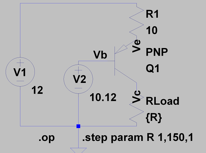
In this circuit, a PNP transistor sources current. The base voltage is about 0.7 V less than the emitter voltage. So with 10.3 V on the base, the emitter has about 11 V and R1 sees about 1 V across it. That sets the current, but this time the load goes from the collector to ground.
When the load resistor is low, it is easy for the circuit to supply the roughly 100 mA required. After all, a 10 Ω resistor only needs 1 V across it to get there. But the circuit can only get the collector to around 11 V. So it stands to reason that somewhere after 100 Ω, things will go bad. You can see that in the chart from the simulation where I stepped the load resistor from 1 Ω to 150 Ω:
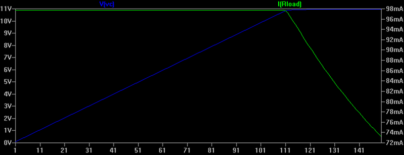
The blue trace (the one that starts in the lower left, for the color blind) is the voltage required to generate the 98 mA through the resistor. The green trace is flat until you get to the 11 V point. Then it drop dramatically as the circuit can supply no more voltage.
All Your Base Voltage
To keep that example simple, I just put a perfect voltage source on the base. But in the first example, I used a voltage divider with a 1 kΩ and 170 Ω resistor. If you did a little math you’d see that 170/(170+1000)=0.15 (about). So with a 12 V supply, you’d think that divider produces 1.8 V. Yet the actual base voltage in that example is about a 1/10th of a volt less.
The reason is simple. R4‘s value is really in parallel with the emitter resistor (R2) times the beta of the transistor. Since R4 is small and R2 times beta is probably pretty big (at least 50,000, I’d guess), the effect is small. However, if R4 were large this could have a serious effect.
By the way, I’m not being lazy about estimating the effective resistance. A transistor’s beta is not a very stable parameter, so whatever the nominal value is, it will vary quite a bit based on current, temperature, and even from device to device.
But Wait, There’s More…
These simple current sources and sinks are pretty useful. However, there are some limitations and there are circuits we will look at in the future that try to mitigate those limitations. For example, FETs can do this quite well, with a bit more math. It is also common to use more than one device to mirror a current — that is, take a reference current and reproduce it. That doesn’t sound useful but think of it as the same as an emitter follower for voltage. The source voltage sees a light load and produces an output voltage that can supply more current than the original source. Same for a current mirror. The reference current might not have a wide range of compliance voltages or — like a resistor — be sensitive to the load. The mirror will present a stable load while providing a more robust output current.
If you want to try an experiment, replace the load resistor on the PNP circuit with a capacitor and run a transient analysis. Just be sure to set the UIC option on the analysis command line (check the box that says skip initial operating point solution). Have a look at the voltage on the capacitor. By varying the current-setting resistor and the capacitor value you can create different straight line charging times. You can find my solution online.


You could stabilize constant current output with an inductor in series with load, for short transients of higher resistance of the load. That would make the current source “stiffer”.
I don’t have many pet peeves, but one of them is rounding off intermediate calculations. I read that a hand calculation would lead me to not expect 1.7 V. Being a bit OCD, I grabbed a calculator, and quickly found that 12*170/1170 was… 1.74? Wait.. why am I not expecting 1.7 V? Finish the article… oh… you rounded 170/1170 before multiplying by 12. Never a good idea. It’s not hard to keep your intermediate results, even with a pocket calculator, so just don’t–you’re asking for trouble if you do.
I remember taking my introductory electronics lab during my physics degree, and seeing lots of students get flustered because they couldn’t even get a simple voltage divider to match their theoretical expectations. They were using the nominal values of the resistors. I measured the actual resistances, and got spot on results every time. That made the experience not only more satisfying, but also a stronger reinforcement of the taught theory.
Moral of the story: don’t round until the end. If you’re going to round anyway, at least do it with an understanding that your numbers are going to be off.
The key to circuit design (or engineering in general) is to recognize what kind of precision is necessary, so that you can simplify calculations where possible. If you attempt to calculate everything exactly, you’ll run out of time.
Often, the realities of the world define how accurate stuff needs to be. If you’re selecting a 5% resistor, you don’t need 3 digits of precision. Also, parameters of semiconductors can be all over the place. There’s no point in precisely modeling the forward voltage of an LED or the current gain of a transistor. Sometimes grasping the concept of a circuit is more important than representing it exactly.
I was going to answer, but Carl hit the points. I don’t know Random so this might not be fair, but I have noticed this seems to be an age thing. When I’m just reasoning about things I frequently just “back of the envelope” the numbers. I’ll crunch at design time, but I’ll say things in a meeting like “6.9 x 3 is just under 21 and…” someone will invariably yell out “No it isn’t it is 20.7.” I was on the phone with a vendor the other day where this was a 3 minute conversation that went “Yeah, just under 21. No 20.7. Right… almost 21. No 20.7.” Like some odd version of “Who’s on first.”
I’m not saying it is right or wrong as long as you are’t messing up significant digits — that’s a whole other topic — but I think if you did math with a pencil and a slide rule, you do tend to just make round numbers to get orders of magnitude in your head a lot. If you grew up with calculators, you want that exact number.
Now significant figures is another issue. If you measure something down to the 1/10 of an inch to be 3.2 inches and you divide it by 3, the answer is NOT 1.0666667 regardless of what your calculator says.But that wasn’t my point, nor Random’s.
No wonder that gets on your nerves! I don’t know who’s at your meetings, but I think a lot of people have the idea that EE is an exact science, maybe because it looks complicated from the outside. In reality, the tolerances are often greater than in mechanical or civil engineering (a 5% tolerance on a resistor might be just fine, the same tolerance on a concrete slab probably isn’t!).
In fact, one more thing. When I talk to high school students about engineering I often say: Your math teacher won’t like this, but for most engineering and science, the real value of math is not getting the exact answer. It is developing intuition about processes. So if I increase this by 2, does that go up by 2? By 4? By 16? Does it go down by 1/2? The exact numbers matter when you are doing the final design, but the real value is understanding that this changes that in proportion to the square, or whatever.
I think y’all missed the point. =)
What I was trying to say was that the “You might have expected this, but turns out…” is indicative of misunderstanding. Both the author and I made the calculation. Al rounded, and ended up with a discrepancy that had to be justified. That need for justification would have been entirely unnecessary by doing the calculation correctly without rounding an intermediate step.
For a beginner, reading something like this justification can be very confusing–as was the case for the students in my class who struggled with the large discrepancies they were getting. They felt like they just weren’t any good at electronics, because they couldn’t get it to “work right”. I was fine with the discrepancies, because I investigated a little further, did it a little more precisely, and *learned for myself that the error is unimportant, but I also understand why the error exists and why it’s unimportant*.
Anyway, this is way off topic now. Hopefully that clears things up for y’all, or at least is noticed by someone who’s fear is reduced a little as a result.
Reading it more carefully, I can see value in pointing out the discrepancy, because it illustrates the point that there is a current junction at the base between R4 and the emitter/R2 series. That discrepancy is small–much smaller than the discrepancy caused by intermediate rounding. The knowledge that the size of R4 can make a big difference and potentially cause problems in a design is what’s important here. But I still stand by my comment–many people may also try hand calculating that junction voltage, and will be less surprised than implied.
The TL431 and a transistor make a cheap, stable current source.
A regulator like an LM117 can regulate the LED current.
A useful trick to know is that the forward voltage on an LED makes a reasonably good voltage reference.
The temp-co is just about the same as for a silicon transistor.
There is a fairly simply way to use this fact to regulate the LED current too
Recently did a current source to measure from 10 to 1000 micro ohms. And did it using less than 2A. The tempco of everything becomes important. As bipolars are worthless for any decent current source, most designs are typically limited to FETs, but few will behave well as a stable linear device. And sensing and gate drive must be 4-wire kelvin stuff. Went through three vendors and at least eight different supposedly zero-drift/low-offset op amp models before things got reasonable. And do not get me started on how most 24-bit ADCs cannot provide more than 17 bits of legit data. Precise and reliable current control is the domain of the most cool humans on the planet. Ask my dog if you do not believe me…
I see a mention of the 80’s here and oddly enough that is reflected in the schematic.
LEDs have changed since the 80’s.
In the 80’s they were comparatively very dull. The Max forward current was then about 25mA and I believe it much the same now for common garden variety LEDs. But back in the 80’s 20mA was lit but not bright. 15mA was lit but dull and 10mA was was just a glow.
The target current in the schematic is 20mA which was the common safe target in the 80’s.
Now almost 40 years later, using modern LEDs, 5 to 10mA is a good choice for an indicator rather than a light source. 15mA is uncomfortable to look directly at and 20mA is burning your eyes out.
Well I’m an old guy, but it was just an example and the current value itself really wasn’t the point. Besides, all the LEDs in my junk box are about 40 years old ;-)
@[Al Williams] I love your articles and the math is the same no matter what the current.
I see the “burn the eyes” LEDs in a lot of “run of the mill” products now.
My bedroom looks like a Christmas tree at night so I cover a lot of the LEDs over.
Maybe… just maybe… I have the patent on these: https://www.amazon.com/LightDims-Black-Out-Electronics-Appliances/dp/B009WSN8PK/ref=sr_1_2?ie=UTF8&qid=1525435513&sr=8-2&keywords=led+covers
Lol… no… I don’t. That’s my story and I’m sticking to it.
Hmm,
for daylight conditions 40mA for diffuse coloured Leds is ideal and at
a good point on the cost curve. Especially suitable at night when the
led is a fuse fail indicator so best it stand out during daylight and to
definitely trigger the wtf response at other times, to be sure as well
as well raise a bit of annoyance ensuring it Cannot easily be missed.
My gang does these now and then leaving me to ‘other things’ I far
prefer be kept out of the public eye & via corporate obfuscation too ????
https://www.ebay.com.au/sch/purple_engine/m.html
Cheers
Not if the LED isn’t specified to run at 40 mA. A safe maximum rating for the typical 5mm plastic bead LEDs is 25 mA. That limitation comes from the thermal dissapation properties of the casing, which limits it to about 100 mW in open air at NTP. Enclosed and in elevated temperatures, you have to de-rate the diode.
Depending on the diode, let’s say a typical green InGaN diode, you got 3.0 – 3.4 V of voltage drop at 20 mA, which make the power dissapation 60 – 70 mW. If you push that to 40 mA It’s going to overheat and dim out, and 40 mA on a simple indicator light is a terrible waste anyhow.
You know Mike, for someone who claims to be a bit of an everything-expert with decades of industry and academic experience, throwing the dictionary into most comments you make – how come you don’t understand how web input forms work? You don’t have to hit enter every time the line is full – that’s how people know you’re a crank.
Is a resistor in parallel with a diode (forward biased normal diode or backward biased zenner) a constant current source? If yes, is it a good one? If no, why?
Why not use a 555 timer? http://www.instructables.com/id/Electronics-Projects-Constant-Current-Power-Suppl/
Note to all:
There is no current shunt here. In the first schematic, R2 would be called a current sense resistor. Again, not a current shunt. If a resistor was placed across the LED to reduce power, THAT would be a current shunt.
No one called it a shunt here, just didn’t want it to turn into this train wreck:
https://hackaday.com/2018/02/08/how-current-shunts-work/#comments
I have a bias for using NPN transistors instead of PNP, so for me sourcing current is the way to go
I have a bias. Transistor pun? :)