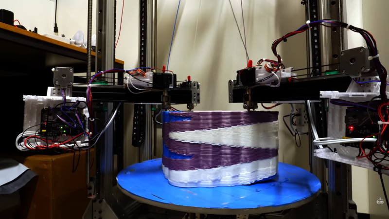
3D printing is all well and good for making low numbers of units, so long as they’re small enough to print in a reasonable time, but what if you want to go really big? Does a 35-hour print time sound like a fun time? Would it even make it that long? [Nathan] from Nathan Build Robots didn’t fancy the wait, so they embarked on a project to build a huge parallel 3D printer with four independent print heads. Well, kind of.
The premise seems obvious at first glance: More print heads mean more plastic is laid down per unit of time. As long as you can maximise the nozzle diameter and machine speed, it should theoretically be possible to speed things up massively. But it doesn’t work like that. The custom machine they constructed utilises a polar coordinate system, with a rotating bed (the ‘theta’ axis) and four radial axis gantries arranged at 90 degrees to each other. Each gantry has its own independent extruder, so multilateral printing is also an upfront option. [Nathan] laments that the problem with constructing such a beast is not so much the mechanical aspects but the limitations in the current firmwares out in the wild. There are also more complex considerations at the slicing level, so getting the machine to operate as desired is quite a large programming task! Right now, this means that each radial axis must operate in lock-step, meaning objects to be printed must be rotationally symmetric of order four. Another option is to print four copies of a much smaller object in parallel, which has its use cases, but that’s not their end goal. [Nathan] says he was going for a record-breaking 20kg print. However, multiple issues with alignment over height and bed adhesion, not to mention keeping the extruders fed with fresh filament, scuppered this first attempt.
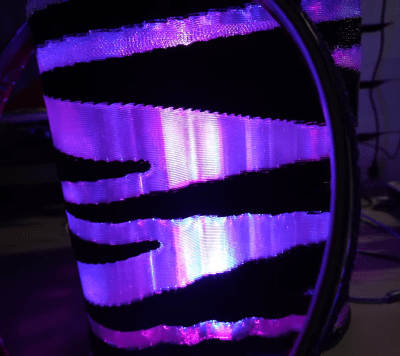
There are some large hurdles regarding alignment. The four corner verticals can be out of alignment with each other in all sorts of ways, causing the radial axis to shift as the Z axis moves. We suspect that’s just one glaring problem, and other more subtle issues are waiting in the wings to cause problems in the future, but we’ll keep an eye on this and see where it goes!
We covered a few projects turning up the 3D printing knobs lately. Here’s a big printer, for big prints. Our thoughts about speed printing and, lastly, a fascinating machine mod that optimises colour swapping by having automated hot end swapping.


wild to me that someone would consider building such a beast and then consider writing new firmware for it as outside of the project scope :)
Consider that the firmware is what turns code into machine movement. I haven’t looked too deeply, but that’s a whole additional layer of “what gcode should cause, and how to turn the steppers to make that happen”. There are lots of codes so it’s not usually quite as simple as “change variable, move motor”, especially if some of the non-linear codes are set up. I’d agree if I knew the guys day job was to program and run old multi axis CNC machines as then it could be assumed he’s starting with that background pool. An additional reason to use existing firmware is that a lot of thought and dev times already been put into safety(thermal runaway, etc.).
Klipper might be the easiest base for the control software development. Considering that the G-code processing occurs on PC side, it is easier to adapt.
But it is hard to figure how this would best fit in the traditional G-code structure. Some possible ways:
A single file with separate “G1 T0” “G1 T1” commands for different toolheads.
Multiple files played in parallel and synchronized somehow
Automatic separation of “G0 G1 … G1 G0” blocks and using the best available toolhead to execute them, while checking if there is non-overlapping following move that can be done simultaneously.
Multi-nozzle extrusion with fast swaps could have some speed benefit from just having separate infill nozzle with different diameter.
My guess is that it’s going to need a slicer to be able to print with those heads like that as well as the firmware.
” As long as you can maximise the nozzle diameter and machine speed, it should theoretically be possible to speed things up massively. ”
No, you need to manage the volumetric flow rate – how fast you can get melted plastic out of the nozzle.
Simply increasing nozzle size speed only works within the limits set by your hotend’s ability to melt plastic as fast as if come through.
Anyone who’s tried to increase speeds or nozzle size hits up on that limit pretty quick – 0.6 mm nozzle is about the best you’ll get out of a standard hotend.
a lot of his speed increase is coming directly from using huge(by hobby standards) nozzles, 4 at a time, so you can probably assume that he’s already thought about how to keep that much filament flowing via the hotends, he said it was a CHT nozzle as well.
And if you move to screw extruder to push out more plastic you run into issue with stopping extrusion meaning that you need to print everything in vase mode. As the volume of melted material increases layer timing becomes important. Layer time too short and the previous layer is not structurally sound, too long and the new layer will not adhere.
There are a lot of challenges to increasing extrusion volume past what current desktop machines can do.
Doing things in parallel is a common way to speed things up.
This has been used for a long time in CNC machines, as an example see this multi-head CNC router:
https://www.youtube.com/watch?v=tF7DJrg_hmc
And similarly with drilling machines for PCB production.
Another interesting way to speed things up is with a multi spindle lathe. Each operation (turning to diameter, making a groove, making a chamfer, etc has it’s own tool and is working on another work piece at the same time. After each operation the whole turret with all the spindles rotates to move all work pieces to the next tooling station.
https://www.youtube.com/watch?v=mBzQHj2xM8c
Similar machines have existed long before CNC machines They were purely mechanical with cams, levers and many adjustment screws.
[Nathan] has a nice printer, but why experiment with this technique on such a big printer? Watching it finish a 20kg trash bin (@04:15) is not only boring, it’s also expensive.
Had to watch the video twice.
My brain couldn’t process the fact he spend 4kg of material on a trash can, that’s about 80euro worth of filament.
People will do anything for “content” / YouTube likes no matter how idiotic.
This is the same guy who made the super-alarmist “CF filament === Asbestos!!! OMFG!!!” video that went viral recently.
Anytime you’re buying filament in the range of 10 rolls or more it costs considerably less. Can get many brands in the $10/kg rate.
Came up with a multi-head 3D printer a few years ago and at the time, Autodesk’s Inventor supported multiple gantries.
https://forums.autodesk.com/t5/inventor-forum/netfabb-configure-printer/m-p/7093765/highlight/true#M644106
Even though my design would support dozens of heads on a room size printer with no sacrifice in XY accuracy (didn’t find anything like it in a patent search at the time), I knew the software was beyond me … too many projects, too little time.
Printing symmetric shapes is just a slight tweak on printing N of the same model in parallel (you could do it purely mechanically). Multiple heads printing a single, unsymmetrical model at the same time would be clearly useful, but then you have a bunch of mechanical and software challenges.
If you were going to use all that extra hardware, and spend years writing a slicer for it, a 5-axis printer with 3D toolpaths would probably be more useful.
This is something I was considering doing for my studio. We are constantly running 50-90 hour prints that are mostly radially symmetrical, I pitched the idea almost a year ago to consider almost the same machine Nathan built here, but because of the funds and resources we had available the idea was archived. It’s a fun idea, and is pretty scalable if done right. In theory you could have as many heads running as your model has radial symmetries