After previously working out a suitable approach to create a period-correct paper tape reader for his tube-based, MC14500B processor-inspired computer, [David Lovett] over at the Usagi Electric farm is back with a video on how he made a working tape reader.
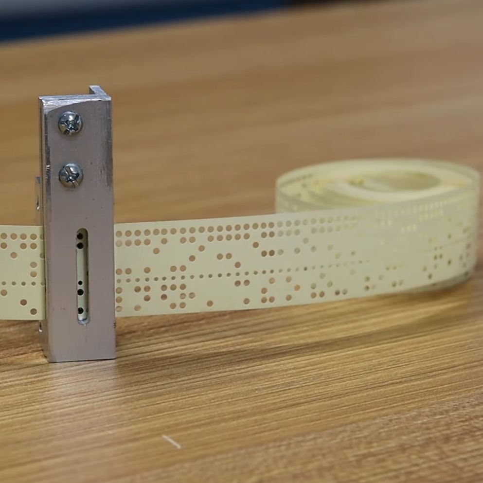
The tape reader’s purpose is to feed data into the tube-based computer, which for this computer system with its lack of storage memory means that the instructions are fed into the system directly, with the tape also providing the clock signal with a constant row of holes in the tape.
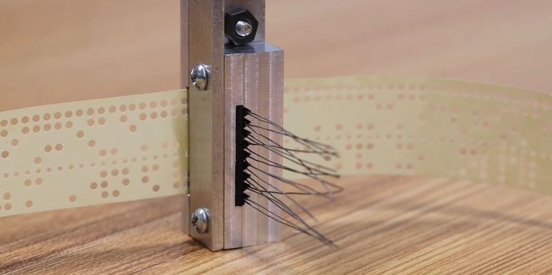
Starting the tape reader build, [David] opted to mill the structural part out of aluminum, which is where a lot of machining relearning takes place. Ultimately he got the parts machined to the paper design specs, with v-grooves for the photodiodes to fit into and a piece to clamp them down. On top of this is placed a part with holes that line up with the photodiodes.
Another alignment piece is added to hold the tape down on the reader while letting light through onto the tape via a slot. After a test assembly [David] was dismayed that due to tolerance issues he cracked two photodiodes within the v-groove clamp, which was a hard lesson with these expensive (and rare) photodiodes.
Although tolerances were somewhat off, [David] is confident that this aluminum machined reader will work once he has it mounted up. Feeding the tape is a problem that is still to be solved. [David] is looking for ideas and suggestions for a good approach within the limitations that he’s working with. At the video’s end, he mentions learning FreeCAD and 3D printing parts in the future. That would probably not be period-correct in this situation, but might be something he could get away with for some applications within the retrocomputing space.
We covered the first video and the thought process behind picking small (1.8 mm diameter) photodiodes as a period-correct tape hole sensor for a 1950s-era computing system, like the 1950s Bendix G-15 that [David] is currently restoring.


I’m not sure why not opt for SMD photodiodes and SMD IR LEDs, but from a purist standpoint a CNC milled block and retro photodiodes makes more sense. It was a nice article and interesting video!
It just took me time to understand why it was machined in this way. I’d probably use a drill and some sheet metal or PTFE for low friction. His design is superior to mine though in longevity.
Because part of the design is that it has to use components that were available in the 1950’s, which was mentioned extensively in the video.
SMD components are therefore completely out of scope.
I’d have used transparent plastic rods as light guides and 5mm CdS photoresistors. Also 100% period correct and much easier to work with.
CdS’s are extremely slow, even at this machines speed it might as well be toggle switches
With proper biasing and signal conditioning a small CdS LDR can do 100 Hz and more. The old farts here might remember the “light telephone” construction projects from yesteryear.
Usagi is a funny guy. Takes a huge chunk of round aluminum and then mills a flat bar out of it… :-)
And you can watch it screaming “Hey, glass with metal and clamping that stuff will end in a disaster.” and moments later there is the disaster.
Overall, his stuff if really enjoyable.
Haha i was wondering what the machining part was, the final piece looks like a L profile with some flat bar pieces lol
Now that’s a paper tape reader https://hackaday.com/wp-content/uploads/2016/08/heath-robinson.jpg
About 50 yrs ago I worked for a UK company made two types of paper tape reader. One used a ‘half-step’ 7.5deg stepper motor on a sprocket with hardened drive steel pins. Worked OK up to 30 steps/s. The other held the tape against a rubber drive wheel. The tape was lifted off the wheel with a sprung-loaded steel ‘shoe’. For each ‘step’ a custom DC solenoid would pull the shoe away to allow the rubber wheel to transport the tape. It was tricky to balance the spring strength, shoe clearance and solenoid current, but speeds of 10 steps/s were possible.
Assuming the reading works fast enough, it seems you could just use a continuous feed system rather than stepping. Then it’s just a matter of matching the feed speed to the expected baud rate.
“period-correct tape hole sensor for a 1950s-era computing system”
What about metal pins and a cup filled with mercury?
Last video he pointed out that physical detectors would cause were on the tape. He’s intnding to run it continually over a few days of a con, so wear willl be a problem.
Reading this article I was wandering if somebody has tried to read old strip-chart graph data. I know it is more complex, but could be very useful. Any hints or links on that?
CCD line sensor and a lens? The line sensors are used in scanners and fax machines, should be readily available, either new or salvage.
These days those are progressively more of a “were”. Epson’s product cycle on prosumer stuff seems to be 10 years or more. And faxes are pretty rare.
I guess the current big consumer of line CCDs is probably still barcode readers? (Or are those just PMTs and signal analysis?) And outside store registers those are converting to 2d sensors for QR codes.
Reading paper tape is relatively easy. What I think the retro computer community needs is a paper tape punch.
This. I am asking myself how is he going to punch the tape, it is a proprietary architecture after all. I wonder if Marc, from Curios Marc has something in stock, they could collaborate again…
I have a paper tape punch, was thinking about a little side hustle punching tapes as a service so I offered free paper tape punching to one of the retro computer forums. I figured they’d eat it up.
zero takers.
Are spools of paper available?
this. paper of the right type is not available anymore. it should be lightly oiled for certain types op punches otherwise the punch block will wear out very fast.
i’ve occasionally mused about tape punches and readers built around ribbons commonly found in fabric stores. recall that konrad zuse started out using old movie film….
similarly, i’ve wondered from time to time about punch/reader equipment built to handle playing cards.
The easiest way in the modern era is probably to get one of those Hazardous High Power Blue Diode Lasers ™ and make a tiny CNC machine to laser cut holes in the paper.
I often thought that the roller mechanism from a thermal printer would be good for paper tape. It seems to grab onto the paper pretty well and some manufactures still offer replacement parts after decades of service.
Many many years ago, my friends and I tried to make a paper tape reader for the PC parallel port. But we ended up having a lot of problems making it work. It’s not that easy to pack everything into a small space and have things come out the right dimensions.
It should be noted that the cracked photodiodes weren’t actually from a tolerance problem, but from a human error problem!
Initially, I had planned on have the V-cut plunge to a depth of 2.3mm, but during machining, I decided it would make clamping a little more secure if the photodiodes set up a little more proud, so I changed my V-cut plunge to a depth of 2.0mm, but my dumb self forgot to readjust the height of the mask holes, so they were drilled with a depth of 2.3mm in mind.
Oops! Lesson learned, don’t change the design on a whim while machining!
Usagi, you can look at and take some idea from this picture https://www.cryptomuseum.com/crypto/ussr/m105/img/301811/002/full.jpg There you can see 4 groups of some small pins, projected above the plate. They are placed on 4 wheels, that are rotated by a stepper motor. Probably, below the plate there are some gear wheels, but I think it will not be a problem for you to guess how they are composed. Very simple and reliable machinery.
I hope this will help you a little.