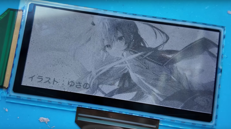
Over the decades the technology behind flat panel displays has continuously evolved, and we’ve seen many of them come and go. Among the popular ones there are a few that never quite made the big time, usually because a contemporary competitor took their market. An example is in a recent [Wenting Zhang] video, a mystery liquid powder display. We’d never heard of it, so we were intrigued.
The first segment of the video is an examination of the device, and a comparison with similar-looking ones such as a conventional LCD, or a Sharp Memory LCD. It’s clearly neither of those, and the answer finally came after a lot of research. A paper described a “Quick response liquid powder” as a mechanism for a novel display, and thus it was identified. It works by moving black and white electrically charged powder to flip a pixel from black to white, and its operation is not dissimilar to the liquid-based e-ink displays which evidently won that particular commercial battle.
The process of identifying the driver chip and pinout should be an essential watch for anyone with an interest in display reverse engineering. After a lot of adjusting timing and threshold voltages the dead pixels and weird effects fall away, and then it’s possible to display a not-too-high-quality image on this unusual display, through a custom PCB with an RP2040. Take a look at the video below the break.
We’ve seen [Wenting Zhang]’s work here a few times before, most recently in a very impressive mirror-less camera project.


Etch-A-Sketch: the original liquid powder display.
15 years ago, my MSc Thesis tried to interface with QR-LPD with custom TFT circuits. As I recall, QR-LPD requires a high electric field to move the ink. At least 150V potential. Higher voltage potential gives quicker response.
I always hoped to see some of the technology be successful in some way or form. This is a nice throwback for me :)
http://ce-publications.et.tudelft.nl/publications/363_a_flexible_electronic_paper_with_integrated_display_driver_u.pdf
This is awesome! Do you know/ can you disclose what happened after you made that 5×5 prototype? I thought that Bridgestone was (at least partially) forced to do passive matrix because it’s quite hard to develop high voltage TFT process/ circuit for it. But passive matrix is just never going to give them the speed they want.
After my thesis, one wafer got sent to Japan to be prepared such that the QR-LPD got glued on top. It took ages before that came back. Under the microscope I might have seen some particles move as part of a passive test. I think other students continued this work. I don’t think they had any success neither. Maybe you might find their work via citations…
I finally got the time to watch your video. Your project is well executed. I don’t have any useful suggestions other than playing around with HV and MV, what is the closest you can get to the threshold voltage?
Thanks! I tried swept through from MV=10V HV=20V to MV=45V HV=90V, the screen starts to respond at around 25/50V. And the sweet spot (highest contrast) I got was around 30/60V to 35/70V
Wenting,
Let’s assume that the passive matrix is the main culprit on the screen performance. Would you be able to assess the contrast by varying the following:
1) line pattern {horizon, vertical, diagonal}
2) line width {1,2..n}
3) pulse duration
I assume that diagonal lines will have issues with cross talk, reducing the contrast.
Maybe for images, you could come up with an algorithm to write the images in layers. I.e. the first update will just do large regions of black and white. Second update will update with white and black. Maybe this will be a bit more resistant to cross talk.
I haven’t thought this through yet: what if you make MV voltage controllable via the MCU. Having +/-5V on your nominal MV might be helpful in getting the cross talk under control.
HaD: Everyone who isn’t our best buddy and pats on our shoulders is our enemy? Seriously?
Sorry, wrong topic.
Supper cool keep up the good work and hope everything goes well I was going to ask if the protocols on The matrix was written with only a specific number of layers in mind or if enough layers could generate 3D imagery. Just some food for thought I never been good with writing protocols for Arduino with basic stuff I’d be so lost with imagery 😅