For those who have not dealt with the automotive side of electronics before, it comes as somewhat of a shock when you find out just how much extra you have to think about and how tough the testing and acceptance standards are. One particular test requirement is known as the “load dump” test. [Tim Williams] needed to build a device (first article of three) to apply such test conditions and wanted to do it as an exercise using scrap and spares. Following is a proper demonstration of follow-through from an analytical look at the testing specs to some interesting hand construction.
The load dump test simulates the effect of a spinning automotive alternator in a sudden no-load scenario, such as a loose battery terminal. The sudden reduction in load (since the battery no longer takes charging current) coupled with the inductance of the alternator windings causes a sudden huge voltage spike. The automotive standard ISO 7637-2:2011 dictates how this pulse should be designed and what load the testing device must drive.
The first article covers the required pulse shape and two possible driving techniques. It then dives deep into a case study of the Linear Tech DC1950A load dump tester, which is a tricky circuit to understand, so [Tim] breaks it down into a spice model based around a virtual transistor driving an RC network to emulate the pulse shape and power characteristics and help pin down the specs of the parts needed. The second article deals with analysing and designing a hysteric controller based around a simple current regulator, which controls the current through a power inductor. Roughly speaking, this circuit operates a bit like a buck converter with a catch diode circulating current in a tank LC circuit. A sense resistor in the output path is used to feedback a voltage, which is then used to control the driving pulses to the power MOSFET stage. [Tim] does a good job modeling and explaining some of the details that need to be considered with such a circuit.
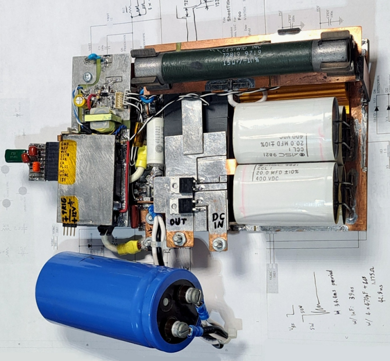
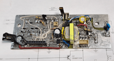
The third and final article turns what’s been learnt so far into a practical design that can be built, with many extra parts added and explained to make this work in reality. It was nice to see ICs being mostly rejected in favour of a discrete design using transistors and other parts at hand—you can see the individual circuit elements if you know what you’re looking for. That said, the venerable 555 timer is in there, doing one of the things it does best: being a trigger timer. The physical construction is done Manhattan-style on a couple of board layers, with some hilariously outsized parts bolted on just because. There’s much to learn from this project, although it will be a tough read for any newcomer to electronics.
While we’re considering building our own instruments, here’s an active load build. EMC testing is one of those areas that can really cause problems. Here’s our guide. We don’t see enough discrete components used in projects these days. Here’s a discrete transistor CPU to admire.


My understanding is that for decades, alternators have had integrated clamping diodes to mitigate this issue.
I did some load dump tests for some work projects about 10 years ago. At the time, it seemed odd to me that a load dump tester could be a low output impedance voltage source (1-Ohm IIRC), while an unclamped alternator that comes disconnected from the load would be more like a current source, where the V = L * di/dt relationship would result in a potential that allows the current to find a path.
For sure, this would have been enormously destructive to any automotive electronics installed in vehicles in the middle of last century.
For alternators with integrated clamping you do Pulse 5b: Clamped Load Dump. Otherwise it’s Pulse 5a: Unclamped Load Dump.
Ah, yes! I had forgotten about the clamped vs unclamped waveforms. I do remember unclamped being 100V, which made for some pretty easy mental math when I captured the voltage waveform of the pulse generator driving the input to a cigarette lighter to USB charger. The 100V waveform immediately drooped to about 60V, indicating that some poor component in the buck regulator was sinking 40A. Shortly thereafter, the component(s) turned to open fuses, and the voltage waveform snapped back to its open circuit shape.
I am sure you are right, but the ISO standard leaves a lot of options as to the exact specs for this pulse. And it should be regarded as a kind of worst case scenario. Imagine what would happen if the 30 – 50 ECUs in your modern car went up in smoke after the battery cable comming off. You’d have a heap of scrap metal.
It might be worth noting that the load dump test was part of ISO 7637-2:2004, but is not in ISO 7637-2:2011. Instead, it can now be found in ISO 16750-2:2012.
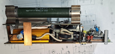
Nice to see copper clad board used so beautifully and for such sn interesting project. This has true homebrew vibes. If you don’t want to fiddle with glue, a useful tool for cutting traces directly into copper clad is a scribe with a sharp metal tip which can be found at most large harderware stores.
The only other ‘near’ ideal current source I’ve run across is current transformer secondary windings in protection circuits. Shorting contacts for test plugs and withdrawable components is a must, otherwise you see a similar voltage rise that can easily breakdown insulation. This leads to a weird situation where if you’re pulling a plug from a test block, and start hearing bacon sizzling, you slam it back in rather than jerking it out to make it safe.
Littelfuse have a good appnote on automotive transients, worth a glance for anyone designing something they want to run in their car – the tl;dr is you need way more headroom than you think even without load dumps etc.
I swear it’s not a bomb officer
11 years ago or so, I built an automotive voltage simulator. It was a job in the heavy duty automotive PC market. We wanted a simulator that could create load dumping or cold cranking events that we could test our device on. I used a weird op amp that could handle high current (4A or so), that was controlled by a Hantek USB arbitrary wave form generator. We designed a wave form on a controlling PC and we could trigger the wave form with a push button switch. I don’t think we could test as high a voltage as this one can, but it worked well for our purposes at the time.
Automotive electronics is where I often see a lot of design mistakes. Most of the time it is simply underestimating the voltage transients that can occur.