
Generally speaking, the Hackaday Supercon badge will always have a place for SAO (rebranded as “Supercon add-ons”), and that makes sense. We did originate them, after all. This year, though, we’ve gone all in on SAO, and, in particular, we’ve asked to see more SAOs with communication capabilities. The standard has always had an I2C bus, but few people use them. I decided I wanted to set an example and cook up a badge for Supercon. Was it hard? Yes and no. I’ll share with you a little about the board’s genesis and the issues I found. At the end, I’ll make you a special offer, if you are going to Supercon.
The Idea
I’ve been a ham radio operator for a very long time. In fact, July was my 47th anniversary in the radio hobby. Well, that’s not true. It was my 47th year with a license. I had been listening to shortwave long before then. So, I wanted to do something with Morse code. You don’t have to know Morse code to get a license these days, but a lot of hams enjoy it.
I set out to do a simple board that would play some Morse code messages. But that’s just another blinking light LED with a buzzer on it, too. So, naturally, I decided it would also provide Morse code output for the I2C host. That is, the SAO could be used to convert ASCII to Morse code. Sounds simple, right? Sure.
Getting Started
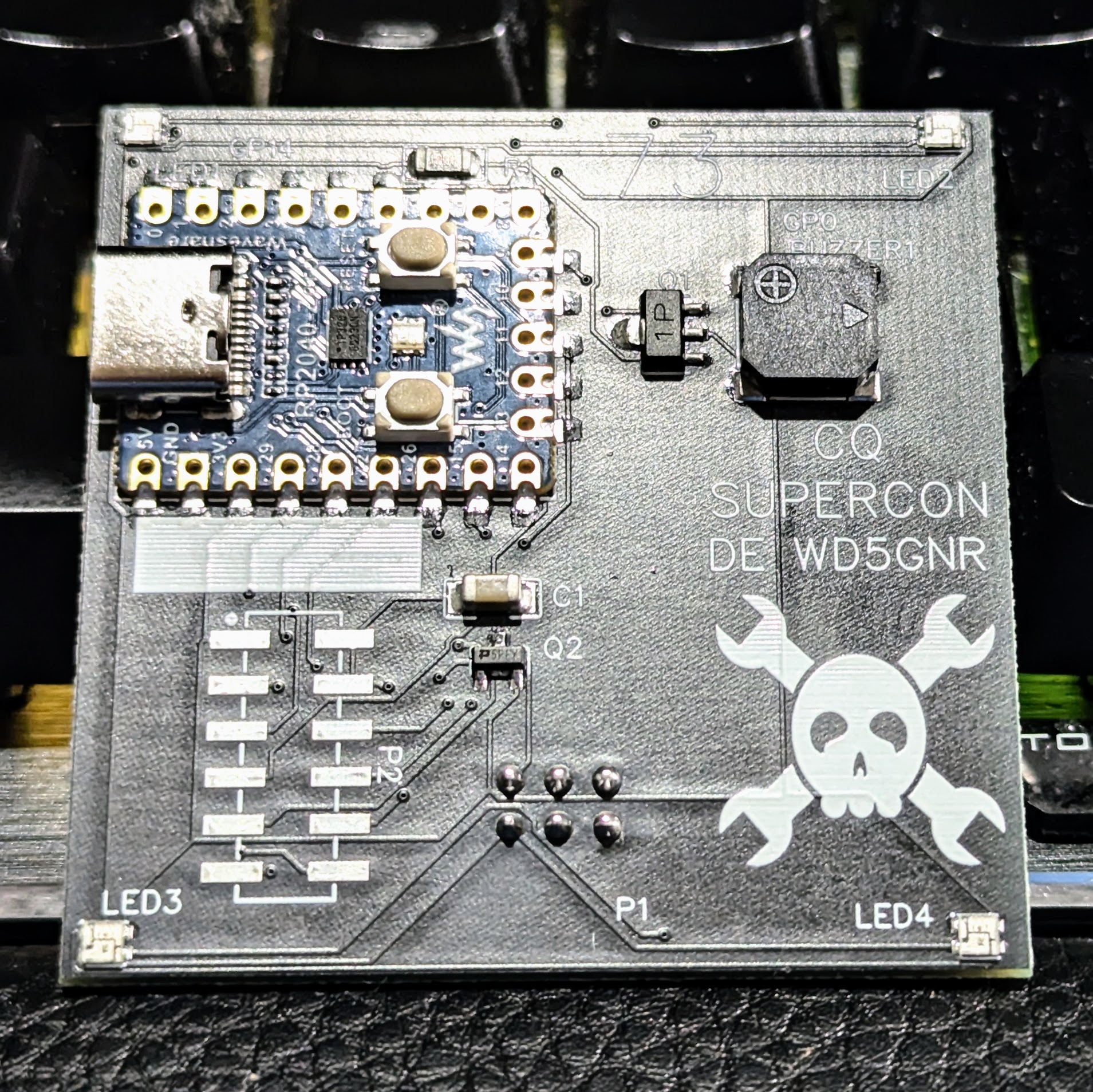
I wanted to use a Raspberry Pi Pico but didn’t want to violate the SAO size requirements. Luckily, there’s an RP2040-Zero module that is quite tiny and looks more or less like a normal Pico. The two big differences are plusses: they have a reset button, and instead of a normal LED, they have a WS2812b-style LED.
Using that let me not worry about a lot of overhead on the board. Sure, it costs a few bucks more, so if you were mass-producing something, that’s not so good. But for this, it was perfect. I only had to add a speaker with a little transistor driver, which is probably unnecessary, four more WS2812B LEDs, and the SAO connector.
I was going to add a button, but I remembered from last year there is a way to use the BOOTSEL button on the module as a normal button, so I decided to cut a corner there. I could have shrunk the board, but I wanted some area for a protyping area and some cool silk screen, since I’m not artistic enough to come up with a nice outline for the board, so I kept the board full-size which is a lot of space.
The only strange thing is that the RP2040-Zero has parts on both sides, so it needs a cutout in the board. No problem. KiCAD didn’t have a good footprint for it that I could find, so I switched over to EasyEDA. They have handy integration with the parts you can get, too, so it is easy to price your board and even buy them already put together if you like.
While I waited for the boards, I decided to grab a similar Pico board and prototype the software. However, in the middle of this, I got a disturbing e-mail.
The Boards are Wrong?
The Chinese board house sent me a note: they were not sure the LEDs were connected properly. I checked, and I double-checked. They looked OK to me. I bravely asked them to build the boards as specified and went back to prototyping.
I’m not always a fan of Python, but we have a history of doing badges in Python so people can easily hack them. So I decided to stick to MicroPython. Getting the code and other features to work was a piece of cake. There is something surreal about using regular expressions to filter comments out of a file on a little microprocessor.
I2C Woe
Once I had the main features working, I set out to do the I2C when I realized an unpleasant fact. The Micropython library has I2C classes so you can host an I2C device. It does not have code that lets you be an I2C device yourself. CircuitPython apparently supports this, but I was in no mood to move the code over. Had I realized it going in, I might have made a different choice.
Luckily, an online forum had some code that directly manipulated the chip’s I2C registers and I was able to adapt that. If you are thinking of building an SAO with I2C capabilities, this is something to check before you go too far.
I stuck with the simple protocol that just lets me receive I2C commands because that’s all I needed, but there were examples of going further. For my project, I created the I2CTarget class. You tell the constructor which I2C bus you want to use, what pins you want to map to, and the I2C address you want to use. There are defaults for all of that.
Once it is running, you can check to see if data is available (call any()) and then read that data (get()). Don’t forget that reading data will block, so if you don’t want to block, check to see if anything is available first. The I2C hardware on the chip has a small FIFO, so that’s fine for this project.
I did create a subclass that allows an I2C object to act like a menu in the code. The menu object normally gets input from the user, but using this little trick lets the I2C commands fake user input.
The Boards Arrive
The board came in, as boards tend to do. I changed a few I/O pins in my code and… big sigh of relief, the LEDs were fine. A few tweaks on the code and the SAO was complete.
I left you all the files and documentation over on Hackaday.io. Maybe I went a little overboard with the documentation. You can decide. The source code is on GitHub, but you’ll find the link on the IO page.
Special Offer
Do you want one? Well, all the design files are there. Fire up your favorite way to etch boards or order them from your favorite board house. It wouldn’t be that hard to point-to-point wire one or put one on a breadboard except for the SAO connector, of course.
However, I have a deal for you. I have a limited number of these and will have them at Supercon. Find me — I’m easy to find since I mostly hang out at the soldering challenge table — and show me some code you propose to run that either uses the SAO or runs on the SAO. If I have any left, I’ll give you one, but when I’m out, I’m out. So, to be on the safe side, maybe make your own and bring it anyway.


” but didn’t want to violate the SAO size requirements.”
I missed that part, now to downsize mine from 3 stacked 15 x 15 cm boards!
B^)
Only if you want it to be produced! If you’re going for the “least DFM” honorable mention, this is a good plan. :)
Al Williams might need to do gamma correction on the neopixel to get a better range of slightly more faithful colours from the LEDS :-)
Funny story. A… “big government client” asked for a yellow LED on a board and had some nanometer range speced that you KNOW the guy pulled off some Digikey catalog page. The board people put a yellow LED that missed the requirement’s nanometer range by like 10nm. This shows up at the sell off and the customer refused delivery until we reworked and requalified the whole thing. The $$(* thing was yellow.
I am trying so hard not to laugh at the pain that must’ve ensued from your funny story. What was the reasoning behind it being that specific nm range? I’m hoping it’s so the bees can see the flowers properly but my guess is because it clashed with someone’s favourite tie/shirt?
Requirements are king. Must meet all requirements no exceptions. The colors on the video are way off and the camera seems to really want to focus on my hand :(
Usually, specs tailor made for a specific brand are linked to brown envelopes with bills inside…
Google “rp2040 i2c slave pio”, follow the rabbit, replace the C hooks by their equivalents in Micropython, job done. And nonblocking
First sentence…. Supercon add on…
That’s not a blinking LED, that’s a (very) QRP tri-band transmitter for the unlicensed 620, 520, and 460 nm bands. Needs a receiver.
MKII eyeballs not sufficient?
In my case being insensitive to yellow, actually, NO
there’s always one ;-) being a neopixel though, the colours should be easily changed for better contrast for your particular case.
I was actually thinking a “DX” contest would be kind of cool. How far can you work it with just the LED and some phototransistors? No optics except R/G/B filters, but spread-spectrum encoding of the CW is fair game. With the right algorithms you can get waaay below the noise floor. Maybe all the way across the exhibit hall?
Please make a reticulum (KISS or PIPE) network device.
Simple plug USB cable to computer and send receive data. Nothing more nothing less
I must be missing something. What is the big deal with converting acii into Morse code. I’ve been a ham since 1965 (you do the math) and have done such converters multiple times since 1977 on assembly language to python. The real challenge is coverting Morse code from audio to ascii.
I wrote a python program to convert ascii strings into morse to help me learn morse. Pretty easy to do. I used chatgpt to generate random sentences that would play through tge program as morse.
Anyway this is all pretty easy. No soldering iron required.
Like the comment before me the trick is to have a program interpret the in coming morse.
Actually, reading isn’t that hard if you have a clean input signal. The goertzel is your friend here along with DSP filtering. Once you have a clean signal you can easily sort it out.