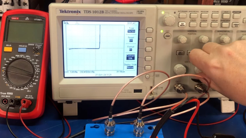
As cheap microcontrollers have given us an impressive range of test equipment trinkets to play with, it’s easy to forget some of the old standabys. A curve tracer for example, the relatively simple circuit allowing the plotting of electronic component response curves on an oscilloscope. Lest we forget this useful device, here’s [Gary LaRocco] with a video describing one that’s so easy to build, anyone could do it.
It’s a simple enough premise, a low AC voltage comes from a mains transformer and is dropped down to the device under test through a resistor. The X and Y inputs of the ‘scope are configured to show the current and the voltage respectively, and the result is a perfect plot of the device’s IV curve. The best part is that it’s designed for in-circuit measurement, allowing it to be used for fault-finding. There’s a demonstration at the end with a variety of different parts, lest we needed any reminder as to how useful these devices can be.
The cost of one of these circuits is minimal, given that the transformer is likely to come from an old piece of consumer electronics. It’s not the first simple curve tracer we’ve seen, but we hope it will give you ideas. The video is below the break.


I once planned to do the same thing … 60 Hz transformer for the x-axis, some FET current sources for the drive steps, and some floating current sensors for the y-axis readout. I went with the DCA75 Pro instead and I love mine. I get a full set of curves on my computer with it.
That’s a very very common and old circuit, the “octopus”. It’s far from being “a perfect plot”, as it’s very slightly biaised.
I think it is easier to do it without a transformer and also nicer when the frequncy is above 50Hz.
https://www.mikrocontroller.net/topic/528893
I have an old analog scope that has a built in octopus. It’s labeled as “component tester”. Also there are the huntron trackers that have dual inputs so if you’re working on say an stereo audio amplifier you can compare parts from the left and right channels to find a fault.