To a lot of us, curve tracing seems to be one of those black magic things that only the true wizards understand. But as [DiodeGoneWild] explains, curve tracing really isn’t all that complicated, and it doesn’t even require specialized test instruments — just a transformer, a couple of resistors, and pretty much whatever oscilloscope you can lay your hands on.
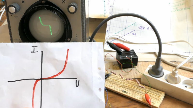
True to his handle, [DiodeGoneWild] concentrates on the current-voltage curves of Zener diodes in the video below, mainly as a follow-up to his recent simple linear power supply project, where he took a careful look at thermal drift to select the best Zener for the job. His curve tracer is super simple — just the device under test in series with a bunch of 10-ohm resistors and the secondary winding of a 12-volt transformer. The probes of his oscilloscope — a no-frills analog model — go across the DUT and the resistor, and with the scope in X-Y mode, the familiar current-voltage curve appears. Sure, the trace is reversed, but it still provides a good visualization of what’s going on. The technique also works on digital scopes; just be ready for a lot of twiddling to get into X-Y mode and to get the trace aligned.
Of course it’s not just diodes that can be tested with a curve tracer, and [DiodeGoneWild] showed a bunch of other two-lead components on his setup. But for our money, the neatest trick here was using a shorted bridge rectifier to generate a bright spot on the curve to mark the zero crossing point. Clever indeed, and pretty useful on a scope with no graticule.


So how does it work with transistors?
The solution shown in the article is only for a two terminal device. To perform a curve trace with a BJT or FET, you would need to control the base current or gate voltage respectively, then take the voltage and current swept over a range. This article has a nice diagram that shows how to use a Tek curve tracer to do so. https://www.electroyou.it/darwinne/wiki/curve-tracing-a-journey-among-devices-characteristics Obviously to do a three terminal device with this solution, you’d need to add circuitry to generate those base current or gate voltage values timed to change at the end of the excursion of each sweep. I don’t envision a real quick and easy way to do that, as setting the various currents and voltages is part of the difficulty. But, perhaps the article might give you some ideas on how to proceed.
It seems like you could use, the ramp output of, one of those nice little cheap function generator chips, [ or dare I say it even the humble 555 ] then match the frequency with the scope. Getting some linearity out of whatever sort of transistory type thing you’re using is probably easier to bias and tweek with a linear driving current for the base to start from.
I’ve used this same curve tracer some 20+ years ago when I was doing repair work, when I had a lot of “the same” PCB’s at hand. The Idea is you have a “known good” version and the “faulty version” and you start poking around with the curve tracer. You see all kinds of weird curves throughout the circuit, but when you probe the two circuits, the curves should be very similar. If you see a big difference, then you are probably close to the fault.
Having a better version (especially higher frequency) shifts the traces, as impedances of capacitors and inductors change.
A very similar technique is used in detecting counterfeit IC’s.
You just start poking around with a more sophisticated version of this (a 50 by 50 ball BGA has just 2500 two-pin combinations) to see if you can find differences between the “good” and “possibly counterfeit” IC. There are test machines which do all the measurements automated. They look a bit like the old fashioned “universal programmers”. Just a big box with a (replaceable) test socket.
After a bit of searching, the process is know as “VI testing” and you’ll find lots of hits on that search term.
That shorted bridge is a good hack.
I always forget about the dwell-time axis in XY mode.
Years ago we called this sort of curve tracer an “octopus” or “oscilliscope octopus.” This video really brought back memories.
A curve tracer can be built using an old transformer and other scrap parts pulled from old boards. The transformer will both supply the necessary voltage and currents plus the driving signal, both for the currents and the scope axes.
Here’s an example: http://techlib.com/electronics/curvetrace.html
Also, don’t miss the much simplified one and the end of the page.
A lot of analog scopes already have this built in. Typically listed as a Octopus or Component Test.
Mr. Carlson’s Lab on YouTube modified an old RCA tube scope to be used as a dedicated Octopus.
You can make two Octopus circuits and use a two channel scope in X-Y. This will have a proper Huntron Tracker. Mostly used with working with audio equipment that such as amplifiers so you can compare one channel to another to find faults.
It’s a great classic hack. I remember building one in the 1960s. Besides diodes, it can also be used with capacitors and inductors, which both generate Lissajous style “oval” waveforms.
A CMOS 4017 is an easy way to generate step functions for testing transistors. The 60Hz can clock the 4017, and resistors on its outputs can produce the base current steps. A diode and filter capacitor provides VDD for the 4017.
Nice, very informative and useful video.
I wonder how it would handle a Gunn diode with negative resistance.
ref: https://en.wikipedia.org/wiki/Gunn_diode
A different hack, but still a bit related.
Two channel arbitrary waveform generators have become quite common and cheap lately (I bought a Chinese one for EUR70 or so) and these can be turned into a transistor curve tracer with a few passives.
Set one channel to a staircase step signal, and the other to a sawtooth with a higher frequency. One sawtooth for each stairs step. I’ve seen this on several websites, and also on youtube video’s.
Nicely done. Never considered the use of a shorted bridge rectifier as a reference