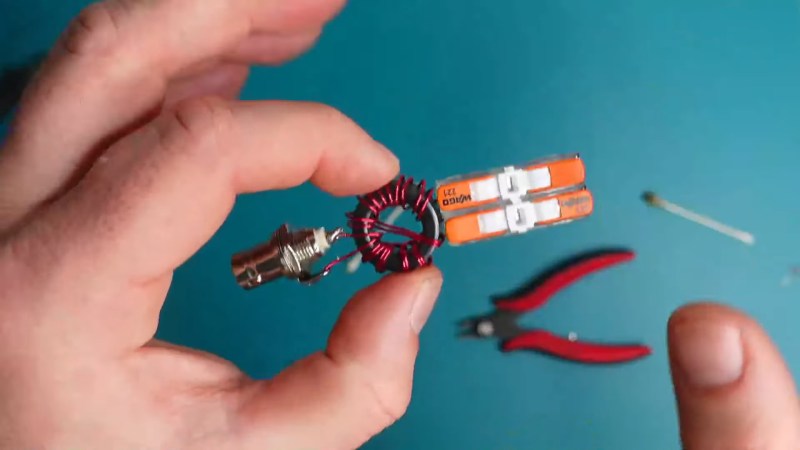
For the amateur radio operator with that on-the-go lifestyle, nothing is more important than having your gear as light and packable as possible. If you’re lugging even a modest setup out into the woods, every ounce counts, which is why we love projects like this packable dipole antenna feedpoint.
At its simplest, a dipole antenna is just two pieces of wire cut to a specific, frequency-dependent length connected to a feedline. In practical terms, though, complications arise, such as keeping common-mode currents off the feedline and providing sturdy mechanical support for the antenna to suspend it safely. [Ham Radio Dude]’s design handles both those requirements while staying as small and packable as possible. The design starts with a bifilar 1:1 current balun, which is wound on an FT82-43 ferrite toroid with 22 AWG magnet wire. One side of the balun is connected to a BNC connector while the other is connected to a pair of Wago splice connectors that are glued together. A loop of paracord for mechanical strain relief is added, and the whole thing gets covered in heat-shrink tubing. The antenna is deployed by attaching a feedline to the BNC, clipping quarter-wave wires into the Wago terminals, and hoisting the whole thing aloft. Full build details are in the video below.
People will no doubt be quick to point out that these Wago terminals are rated for a minimum of 18 AWG wire, making them inappropriate for use with fine magnet wire. True enough, but [Dude] was able to get continuity through the Wagos, so the minimum gauge is probably more of an electrical code thing. Still, you’ll want to be careful that the connections stay solid, and it might pay to look at alternatives to the Wago brand, too.


I love prototyping with Wago! I’ve used them for several ham radio projects.
https://www.instagram.com/p/COEpFbajD9z/?img_index=1
https://www.instagram.com/p/CaLjtParjDr/?img_index=1
https://www.instagram.com/p/CkXOwKTjjAe/
Small and light doesn’t need to be that flimsy.
My SOTA setup is similar! It’s a balun piggybacked onto a BNC-to-Banana terminal, feeding a linked dipole. The links are knockoff wagos – they “let go” under just the right amount of force to keep the wire from getting broken. That’s important when you’re using the lightest wire you can manage, and don’t want to bring a whole spool of extra wire.
Type 31 is a FAR better ferrite mix for a choke balun than the type 43 he uses. Type 43 is low loss, which makes it valuable for a transformer but in this application it can potentially form a series resonant circuit with the interwinding capacitance that defeats the choke function entirely. Type 31 is designed to have inherent broadband loss, which of course in this application only (and desirably) exists for common mode currents.
I would build it on a PCB or put it in a 3D printed case. Those wires are going to break off the BNC with a bit of use.
You could pot that portion with epoxy for mechanical support if needed. I’m not sure a PCB would be a surefire solution.
You could put in a small case and use 316 instead of enameled wire with exposed joints. Just saying.
Prototyping with Wago 221 is a method I also use. I have silicone insulated wires with both ends stripped and tinned. Ferrules would be a bit better, but for good contact in the Wago’s you’d need ferrules that are a bit longer then standard (12mm or 15mm instead of 10mm). My wires have lengths starting from about 100mm. This is much more convenient then the 400+mm wires with big chunky banana connectors, and they are almost as quick to use. On top of that, you have the extra reliability because it’s not easy to pull the wires out of them. I use this for any quick prototype that does not fit on a breadboard, for example a high current H-bride or SMPS circuit for several amperes.
The main limitation is longevity. After about 300 cycles the Wago’s start to fatigue and the clamping force diminishes. When you notice that the spring tension diminishes, it’s time to throw them away and use another. But it’s not a big problem, just buy a box of Wago’s and accept that each time you lift the leaver, you have about 0.2ct of cost due to metal fatigue.
I’d probably yeet a particular wago connector in anger long before I got up to 300 lever actuations just because of how often they end up pinching my fingers. At least for the older style ones, I don’t know what these ones are like.
Can we have an honest talk about 1:1 current balun / choke winding? There’s a lot of information and I’m getting the sneaking suspicion that the common knowledge isn’t really right. The particular balun shown here is what is generally recommended, or at least shown a lot, but I’m not convinced it’s the best when you do the Pepsi challenge against a pair of wires around a toroid, without having the little zig that makes half the coil wound one way and the other reversed. Not from a loss standpoint, not from an RF in the shack standpoint.
Instead, the world has a lot of project boxes, PVC pipes, hardware store detritus and bad websites saying only THAT the thing they’re selling works, but not why or how.
Then I see brilliant little projects like this one and that it’s a great opportunity to test all sorts of different configurations, one variable at a time. Nice work.
Wagos do in fact make everything better
If I’m using small gauge wire, I just fold the end over and double it, them insert the doubled up end into the Wago. Seems to work just fine that way for low voltage and stuff like this. I wouldn’t recommend it for line voltage applications however, lol.
Thanks for the Talk, Ted!