When you’re spitting out G-Code for a 3D print, you can pick all kinds of infill settings. You can choose the pattern, and the percentage… but the vast majority of slicers all have one thing in common. They all print layer by layer, infill and all. What if there was another way?
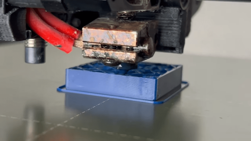
There’s been a lot of chatter in the 3D printing world about the potential of non-planar prints. Following this theme, [TenTech] has developed a system for non-planar infill. This is where the infill design is modulated with sinusoidal waves in the Z axis, such that it forms a somewhat continuous bond between what would otherwise be totally seperate layers of the print. This is intended to create a part that is stronger in the Z direction—historically a weakness of layer-by-layer FDM parts.
Files are on Github for the curious, and currently, it only works with Prusaslicer. Ultimately, it’s interesting work, and we can’t wait to see where it goes next. What we really need is a comprehensive and scientific test regime on the tensile strength of parts printed using this technique. We’ve featured some other neat work in this space before, too. Video after the break.


Unclear: How is this an improvement over (say) cubic infill, or even conventional gyroid?
Really gotta make sure your travels avoid the infill mountains you create this way too.
Varying the z high during an infill ‘slice’ (or layer) will add strength protecting against shearing weakness on the z-plan. Mainly since the layer boundary joins (where the melted plastic sticks to the cool plastic) will no longer all be on the same plane for a given layer.
You could do this with cubic infill or other infills to improve z strength.
I swear I’ve seen posts on this for at least the last 10 years.
seperete—>separate
This post will [hopefully] self-destruct.
I’m new to Prusa Slicer. How would I add this? Where would I put the python arguments mentioned in the git repo.
You’re supposed to call it after generating the G-code, from a command line processor like Windows Terminal or Command Prompt. First you need Python installed: just type “python” or “python3″, or look for instructions on how to install and run it. Once you know where it is, you experiment with the parameters and add your G-code file as the last argument.
python.exe” “C:\Path\To\Script\nonPlanarInfill.py” -frequency 1.5 -amplitude -0.2 my_file.gcode
Is there already an article for this: I would love to see a (possibly very crude) multi-material printer which has a second head which can pour some kind of epoxy or glue (maybe just sand??) to fill the voids in the infill very quickly and cheaply, instead of having to spend the time and filament for 100% concentric infill.
It wouldn’t even have to happen after every single layer–it could do a pass every five or ten layers and calculate the volume of the voids in the infill. Just dump it in there.
It would require some trial and error at first, but it seems so doable that I suspect somebody has already done it. You could do it manually by pausing your printer and pouring it yourself every few minutes, but I don’t wanna do that.
I think the issue there is that the devil would be in the details – outer shells aren’t reliably watertight, fast-curing resins are (highly) exothermic, etc. – whereas it’s easy to inject all sorts of fillers into a finished print, which is certainly a thing people do.
Intumescent resins work well for this (e.g. Smooth-On’s Foam-It series), or for large objects you can use expanding wall cavity insulation. Gypsum plaster is good if you want it to be heavy.
I feel like I read a comment similar to this with an interesting suggestion of leaving small voids for a few layers that the hotend would come back and sort of injection mold into.
That seems like it could be done and have good results.
Though worst case there is always using gyroid infill and filling it with something like epoxy (since it’s all connected internally) at the end.
The issue with leaving voids then trying to inject them is air entrapment. Unless you design these voids with ventlines you end up with compressed gasses pushing back against the molten plastic. Correct procedure for filling blind holes is to insert a smaller diameter syringe needle to the bottom of the hole and withdraw as material is fed in allowing gas to escape.
I print in PETG and TPU exclusively, which have near-perfect layer adhesion. Why would I want to burn out my Z axis leadscrews and potentially crash my print head for negligible gains? If I need strength I’ll just print at 100% infill or mill the part out of metal.
So you don’t need it. Fine. How about just skipping the article, or alternatively stop yourself from posting something irrelevant after reading it? Because the fact that you don’t need something optional is indeed irrelevant.
“stop yourself from posting something irrelevant after reading it? ”
Says the troll who has contributed nothing but extraneous commentary to the thread
It’s all to the good, but let’s be real, infill borders on being a total waste of time and plastic. It’s even worse value than external support. Seriously, I’ve printed entire parts and not even noticed that I had infill set to 0% – that’s how consequential it isn’t most of the time (unless your part has places that would collect rainfall).
The bigger win for non-planar printing would be when it eliminates support material altogether.
(Also, surely infill only adds strength in compression? If your infill layers are in danger of separating, your part has already failed)
What are you printing? Gotta be some very simple shapes to accidentally use zero infill with no issues.
Infill also adds torsional rigidity.
But I agree that this slight waviness doesn’t seem like it would improve things that much, as each individual string of infill is still only connected in one plane. So there can still be layer separation, just that the seam is wavy instead of straight. This is different than the “brick stacking” slicing featured previously on Hackaday, where the different layers bond sideways between strings of extrusion.
It’s also true that pull resistance comes mostly from the perimeters.
“So there can still be layer separation, just that the seam is wavy instead of straight”
This is an EXCELLENT point. I’d be curious what vigorous testing might reveal, but I suspect you’d be correct.
I found that infill only affect strength in big flat areas, and only in compression. Wall thickness and height is more important everywhere else, also including those flat areas. I take infill only as internal print support, nothing more.
Planar infill is only beneficial in the conditions you describe. The point of this technique is to use NonPlanar infill to avoid sheer failure along layer lines by interupting their continuity across the part.
“shear”
Thank you pedantic editor. Your 3rd grade teacher would be proud. Typing with fat thumbs and 50 year old eyes lets a bit through despite autocorrect. Im so glad the internet has kids like you proofreading, no one would have been able to comprehend my words without you. Good JOB! Gold Star!
If it were a mere spelling error it’s unlikely a stable person would comment on the correction like their reputation were at stake.
Get a pair of glasses and slim down if typing is a problem for you?
Idiot.
TenTech is absolutely killing it with all these 3D printing mods right now.
People can debate the finer points of them but the fact we have these things available to play with in the first place is all to the good.
Also shows the power of enabling an open interface in your software so that people can come up with mods like this in the first place.
“it only works with Prusaslicer.”
No, it is a post-processing script, i.e. it is executed after the slicer has finished. The Pruza slicer offers an import option, but in principle it should be possible to use the Python script on any G-code generated in any way. The only requirement is a Python environment.