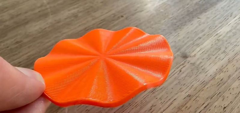
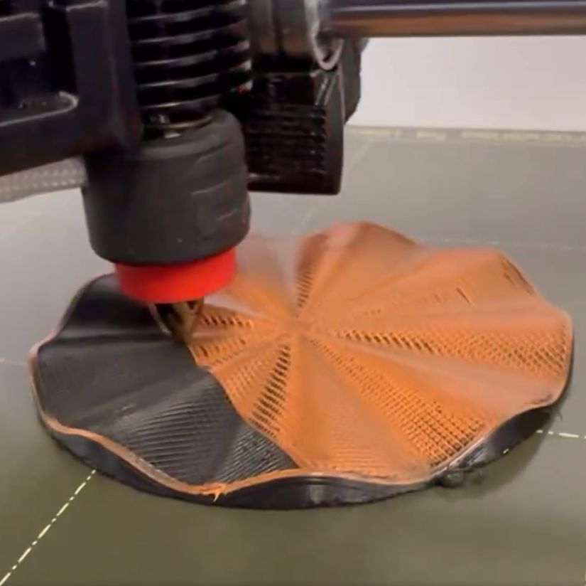
Most of the time FDM 3D printing involves laying down layers of thermoplastics, but the layer lines also form the biggest weakness with parts produced this way. Being able to lay out the lines to follow the part’s contours can theoretically strengthen the part and save material in the process. Recently, [Michael Wüthrich] demonstrated an approach that uses a modified Prusa Mini FDM printer to first lay out a part in PETG using non-planar printing, after which this PETG part was used to print on top of in PLA, effectively using the PETG as a ‘printbed’ from which the PLA can be easily removed and leaving the PLA part as fully non-planar on both sides.
The modification to the Prusa Mini printer is covered on Printables along with the required parts. The main change is to give the nozzle as much clearance as possible, for which [Michael] uses the E3D Revo belt nozzle. This nozzle requires a custom holder for the Prusa Mini. After this the printer is ready for non-planar printing, but as [Michael] notes in the Twitter thread, he did not use a slicer for this, as none exists. Instead he used Matlab, a custom script and a lot of manual labor.
Non-planar FDM printing has been covered by us before, along with the need for slicers which can handle such more ‘exotic’ tasks. Hopefully with efforts like this by [Michael] such a future may be a bit closer now. If the waiting for this takes too long, or 3 axis printers seem a bit old-school, we were reminded via a tip by [Keith Olson] that it’s always possible to double the number of axes for more freedom, as in this video demonstration by [Fergal Coulter] (also embedded below), of a 6-axis 3D printer which also prints on top of an existing substrate.


I wonder if a low-hanging fruit might not be non-planar infill for a slicer. The slicer could look for tall rectangular prism areas inside the object, and then add a bit of a non-planarity to the infill inside this area, thereby increasing strength.
Or perhaps use breakaway PLA supports instead of PETG, which requires a material change and fairly high temperatures
PLA and PETG won’t adhere to each other – it’s why we already use PLA to support PETG (and vice versa) – cheaper than breakaway or dissolvable.
Check out Real3DFFF (https://github.com/seeul8er/Real3DFFF). It is based off the idea described in the Hackaday article from the 27.07.2016, but offers much better usability and some signifikant improvements including computation of normal vectors etc.
Another approach for non-planar-slicing is Fullcontrol ( https://fullcontrolgcode.com/ see some examples at https://fullcontrol.xyz ).
It is basically a Python-Lib for generating gcode directly from mathematical formulas and path descriptions in python code. More the programmers approach: a bit like openscad, but in python syntax and without the detour via a step or stl model and a slicer.
This goes way beyond the established peelable PETG+PLA combination – here’s why:
The non-planar PETG mold or substrate is printed first.
The printed object releases from the mold, while the mold stays on the print bed and can be reused multiple times.
It’s also not low density and not intended to break. It can however be made as a separate piece and bolts to attachment points printed onto the flat print bed. That way, the PETG mold can be flexible and ensure the part can be extracted without damage.
At slow first non-planar object layer speeds, the mold surface texture is also transferred onto the object, which means now you can print objects horizontally, but with tangential, smooth layers all around, and without expending support material.
With PLA-CF for example, this means one can print smooth plane wings, fan blades and drone props that are strong under tension but have no form limitations, all while having smooth surfaces on both sides.
My hope is that this added capability is what allows non-planar slicing to see the work it needs to become mature. I imagine one would then be able to design a model plus a set of non-intersecting curved surfaces that instruct the slicer how layer need to be formed, and it would fill in the spaces in between.
For example, take a 3-blade plane propeller. We know that there need to be fibers oriented along the length of each blade, but at the hub, the layers must transition into a triple-start helical screw for best mechanical performance. Indeed, such layer orientation is approximated by commercial products, which have overlapping helical sections over which they bolt to a hub.
Of course it’s not a panacea, but at least one can see a path towards high strength engineered components with good surface finish, and the more hands-on the printing process becomes, the better our understanding of how to describe the layer orientation constraints and how to automate the path generation will become.
Remember when 3d printing was considered to be less complex technology than subtractive manufacturing? Pepperidge farm remembers.
It’s still a heck of a lot less complex from a user perspective! I hear CNC programming is still a full time job, with 3DP there’s just design and maybe a few minutes to set up the print with your modifier cubes.
That’s awesome! Amazing things are still to come in 3d printing.