A 3D printer is shown, with the print bed pitched sharply toward the camera. The hotend is depositing plastic on a model at a sharp angle to the print bed.

Multicolor 5-Axis 3D Printing

Usually, when we see non-planar 3D printers, they’re rather rudimentary prototypes, intended more as development frames than as workhorse machines. [multipoleguy]’s Archer five-axis printer, on the other hand, breaks this trend with automatic four-hotend toolchanging, a CoreXY motion system, and print results as good-looking as any Voron’s.

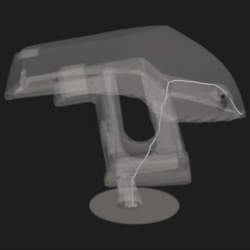
The print bed rests on three ball joints, two on one side and one in the center of the opposite side. Each joint can be raised and lowered on an independent rail, which allows the bed to be tilted on two axes. The dimensions of the extruders’ motion system limit how much the bed can be angled when the extruder is close to the bed, but it can reach sharp angles further out.

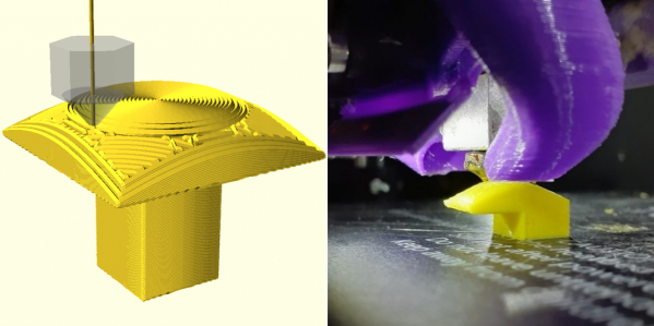
The biggest difficulty with non-planar printing is developing a slicer; [multipoleguy] is working on a slicer (MaxiSlicer), but it’s still in development. It looks as though it’s already working rather well, to the point that [multipoleguy] has been optimizing purge settings for tool changes. It seems that when a toolhead is docked, the temperature inside the melt chamber rises above the normal temperature in use, which causes stringing. To compensate for this, the firmware runs a more extensive purge when a hotend’s been sitting for a longer time. The results speak for themselves: a full three-color double helix, involving 830 tool changes, could be printed with as little as six grams of purge waste.

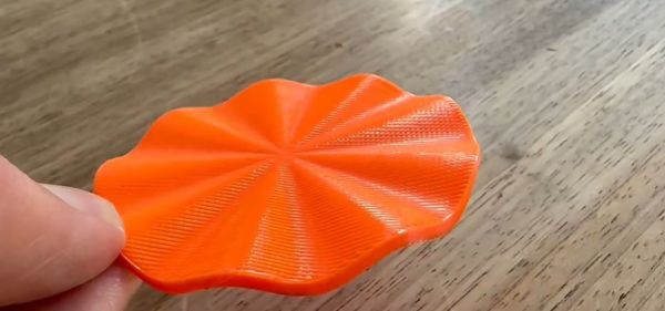
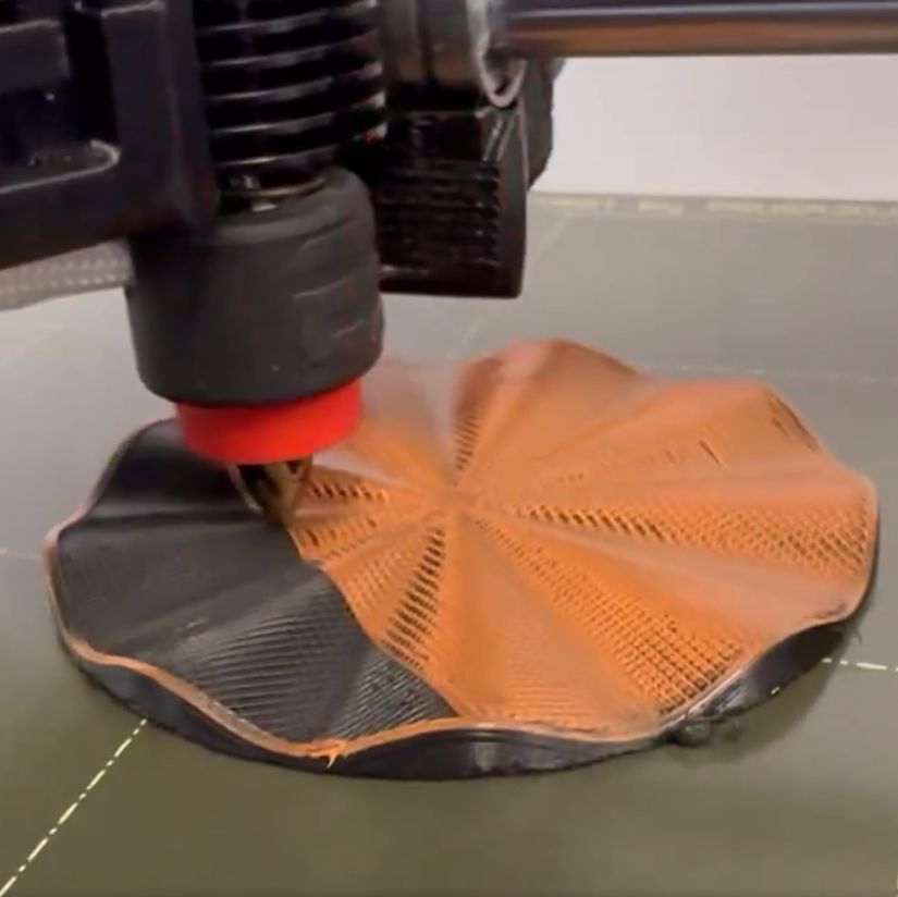
As three-axis 3D printers become consumer products, hackers have kept looking for further improvements to make, which perhaps explains the number of non-planar printing projects appearing recently, including a few five-axis machines. Alternatively, some have experimented with non-planar print ironing.

Benchy, printed upside down on [Josh's] Core R-Theta printer.

Non-planar Slicing Is For The Birds

When we say non-planar slicing is for the birds, we mean [Joshua Bird], who demonstrates the versatility of his new non-planar S4-Slicer by printing a Benchy upside down with the “Core R-Theta” printer we have featured here before.

A benchy model, upside down, with the path from the end of the prow to the printbed highlighted.
S4 slicer uses the path from any point (here, Benchy’s prow) as its basis…

This non-planar slicer is built into a Jupyter notebook, which follows a relatively simple algorithm to automatically generate non-planar toolpaths for any model. It does this by first generating a tetrahedral mesh of the model and then calculating the shortest possible path through the model from any given tetrahedron to the print bed. Even with non-planar printing, you need to print from the print-bed up (or out).

Quite a lot of math is done to use these paths to calculate a deformation mesh, and we’ll leave that to [Joshua] to explain in his video below. After applying the deformation, he slices the resulting mesh in Cura, before the G-code goes back to Jupyter to be re-transformed, restoring the shape of the original mesh.

… to generate deformed models for slicing, like this.

So yes, it is G-code bending as others have demonstrated before, but in a reproducible, streamlined, and straightforward workflow. Indeed, [Josh] credits much of the work to earlier work on the S^3-Slicer, which inspired much of the logic and the name behind his S4 slicer. (Not S4 as in “more than S^3” but S4 as a contraction of “Simplified S^3”). Once again, open source allows for incremental innovation.

It is admittedly a computationally intensive process, and [Joshua] uses a simplified model of Benchy for this demo. This seems exactly the sort of thing we’d like to burn compute power on, though.

This sort of non-planar 3D printing is an exciting frontier, one which we have covered before. We’ve seen techniques for non-planar infill, or even to print overhangs on unmodified Cartesian printers,  but this is probably the first time we’ve seen Benchy given the non-planar treatment. You can try S4 slicer for yourself via GitHub, or just watch the non-planar magic in action after the break. Continue reading “Non-planar Slicing Is For The Birds”

Could Non-Planar Infill Improve The Strength Of Your 3D Prints?

When you’re spitting out G-Code for a 3D print, you can pick all kinds of infill settings. You can choose the pattern, and the percentage… but the vast majority of slicers all have one thing in common. They all print layer by layer, infill and all. What if there was another way?

There’s been a lot of chatter in the 3D printing world about the potential of non-planar prints. Following this theme, [TenTech] has developed a system for non-planar infill. This is where the infill design is modulated with sinusoidal waves in the Z axis, such that it forms a somewhat continuous bond between what would otherwise be totally seperate layers of the print. This is intended to create a part that is stronger in the Z direction—historically a weakness of layer-by-layer FDM parts.

Files are on Github for the curious, and currently, it only works with Prusaslicer. Ultimately, it’s interesting work, and we can’t wait to see where it goes next. What we really need is a comprehensive and scientific test regime on the tensile strength of parts printed using this technique. We’ve featured some other neat work in this space before, too. Video after the break.

Continue reading “Could Non-Planar Infill Improve The Strength Of Your 3D Prints?”

Non-planar Ironing Makes Smooth Prints

If you want to smooth out the top surface of your FDM 3D prints, you can try ironing. Many slicers allow you to set this option, which drags the hot printhead through the top surface with a tiny bit of plastic to smooth out the extrusion lines. However, a recent paper explains how non-planar ironing can provide a better result.

Usually, non-planar printing requires rotating the print bed in addition to the normal linear motion. However, you can also manipulate the layer height in real time to create bulges in the 3D print. This is the approach taken by Curvislicer, which shares authors with this paper. Another approach is to build a part conventionally but add non-planar printing to the last few layers.

The non-planar ironing is a variation of the latter technique. After slicing, the top layer of g-code passes through a Python script. The results on a test object look very impressive. We’d be interested to see how some more complex shapes look, though.

Of course, it looks like all you need is an ordinary printer, a modified copy of Slic3r, and the script, so if you try it yourself, let us know what you think. It would be great to smooth prints without extra chemicals and post-processing. While you can get good results, it is a lot of work.

Still Up And Coming: Non-Planar FDM 3D Printing With 3 Or 6 Axes

Printing the non-planar PLA part on top of the non-planar side of the PETG part. (Credit: Michael Wüthrich)

Most of the time FDM 3D printing involves laying down layers of thermoplastics, but the layer lines also form the biggest weakness with parts produced this way. Being able to lay out the lines to follow the part’s contours can theoretically strengthen the part and save material in the process. Recently, [Michael Wüthrich] demonstrated an approach that uses a modified Prusa Mini FDM printer to first lay out a part in PETG using non-planar printing, after which this PETG part was used to print on top of in PLA, effectively using the PETG as a ‘printbed’ from which the PLA can be easily removed and leaving the PLA part as fully non-planar on both sides.

The modification to the Prusa Mini printer is covered on Printables along with the required parts. The main change is to give the nozzle as much clearance as possible, for which [Michael] uses the E3D Revo belt nozzle. This nozzle requires a custom holder for the Prusa Mini. After this the printer is ready for non-planar printing, but as [Michael] notes in the Twitter thread, he did not use a slicer for this, as none exists. Instead he used Matlab, a custom script and a lot of manual labor.

Continue reading “Still Up And Coming: Non-Planar FDM 3D Printing With 3 Or 6 Axes”

3D Printing 90° Overhangs With Non-Planar Slicing

When slicing a model for 3D printing, the part is divided into a stack of flat, 2D layers. But there’s an alternative in the form of non-planar slicing, where the layers can follow 3D curves. [Rene K. Mueller] took this a step further and successfully used non-planar slicing to print 90° overhangs on a normal Cartesian FDM printer.

Non-planar layers have been around for a while, but were generally limited to creating smooth curves without layer lines. The idea of using the technique for overhangs had been floating around in [Rene]’s head for a while, and he was spurred to action after seeing the rotating tilted nozzle printer featured here on Hackaday. The idea is only to have the outer edge of each layer overhang, by making each layer slope downward toward the overhang. [Rene] programmed a conic slicer algorithm for this purpose, which splits the model into dome-shaped layers, like an onion.

He did a lot of testing and documented the results in detail. Conical slices were compared with tilted slices, which are also used for belt 3D printers. Both have some geometric limitations. Tilted slices can only print the overhang in one direction, but conical slices can do this in all directions, allowing it to create a mushroom-like shape without any support. The limitation is that it can only print inward or outward from a central point. More complex geometry must be segmented, and each sub-volume sliced separately. The slicing angle is also limited by the shape of the print head, to avoid it crashing into the print.

We think this technique has a lot of potential for widespread use, especially since it is compatible with most existing FDM printers. It is still a work in progress, but support has already been added for Slic3r and Prusa Slicer. We look forward to seeing how it develops and gets adopted.

Hackaday Podcast 035: LED Cubes Taking Over, Ada Vanquishes C Bugs, Rad Monitoring Is Hot, And 3D Printing Goes Full 3D

Hackaday Editors Mike Szczys and Elliot Williams get caught up on the most interesting hacks of the past week. On this episode we take a deep dive into radiation-monitor projects, both Geiger tube and scintillator based, as well as LED cube projects that pack pixels onto six PCBs with parts counts reaching into the tens of thousands. In the 3D printing world we want non-planar printing to be the next big thing. Padauk microcontrollers are small, cheap, and do things in really interesting ways if you don’t mind embracing the ecosystem. And what’s the best way to read a water meter with a microcontroller?

Take a look at the links below if you want to follow along, and as always tell us what you think about this episode in the comments!

Take a look at the links below if you want to follow along, and as always, tell us what you think about this episode in the comments!

Direct download (60 MB or so.)

Continue reading “Hackaday Podcast 035: LED Cubes Taking Over, Ada Vanquishes C Bugs, Rad Monitoring Is Hot, And 3D Printing Goes Full 3D”