Determining that a cable has a broken conductor is the easy part, but where exactly is the break? In a recent video, [Richard] over at the Learn Electronics Repair channel on YouTube gave two community-suggested methods a shake to track down a break in a proprietary charging cable. The first attempt was to run a mains power detector along the cable to find the spot, but he didn’t have much luck with that.
The second method involved using the capacitance of the wires, or specifically treating two wires in the cable as the electrodes of a capacitor. Since the broken conductor will be shorter, it will have less capacitance, with the ratio theoretically allowing for the location of the break in the wire to be determined.
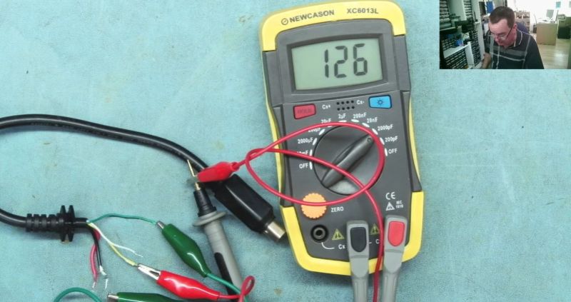
In the charging cable a single conductor was busted, so its capacitance was compared from both sides of the break and compared to the capacitance of two intact conductors. The capacitance isn’t much, on the order of dozens to hundreds of picofarads, but it’s enough to make an educated guess of where the rough location is. In this particular case the break was determined to be near the proprietary plug, which ruled out a repair as the owner is a commercial rental shop of e-bikes.
To verify this capacitor method, [Richard] then did it again on a piece of mains wire with a deliberate cut to a conductor. This suggested that it’s not a super accurate technique as applied, but ‘good enough’. With a deeper understanding of the underlying physics it likely can be significantly more accurate, and it’s hardly the only way to find broken conductors, as commentators to the video rightly added.
Thanks to [Jim] for the tip.


Is it possible to do time domain reflectometry with a VNA? I’m genuinely not knowledgeable enough to be sure lol, maybe it wouldn’t work well on relatively short cables without a purpose built TDR
VNA is frequency domain so you’d need to do an inverse fourier calc so yes it would be possible. I think the industry approach is time domain reflection.
You could also put a known length of cable in front of of the TDR known as a launch cable to get on top of the fault.
The NanaVNAsaver software does TDR out-of-the-box. Driving a standard NanoVNA you can get resolutions down to a couple of cm, and range to many tens of meters.
But if all you got is a capacitance meter, this is a fine hack.
Is it relatively user friendly? If so I’m going to buy one right now.
Yes, dead simple to use if you know what it’s for. Prescribing the right scan for TDR could be simpler, but it’s totally usable.
TDR works great for more real case, like finding the break in one of these buried wire for robot perimeters… nice hack to compare capacitance ratio through
~1ns per foot. You’ve got to be able to send out a very brief pulse and then count pretty fast until you see it reflect back.
Correct and true if you’re working in the time domain.
But the VNA works in the frequency domain, up to 4 GHz (0.25 ns period), and can measure phase to a small fraction of a radian ( a few degrees), so the precision is a fraction of that 0.25 foot.
You actually made sense , where as I thought you were blowing smoke to begin with….ty
The commercial 2 way radio industry uses a measurement called “DTF” (Distance To Fault), there are specific instruments built for that purpose (often incorporated into a test set used for RF measurements). The FDR measurement is a frequency domain sweep that exposes perturbations or irregularities in the cable. We usually use one on a new spool of transmission line, prior to running it up the tower to make sure there are no faults on, say a 300 foot cable lenth.
Tek had an old school TDR set that applied voltages to the line, had a strip chart recorder built into it as well. Can’t recall the model number, but the new sets from say Anritsu are generations ahead of old school TDR’s (that if improperly used could fry expensive tower top amplifiers).
I used to test computer cables and that was how I did it. I used a pulse generator, an oscilloscope and a resistor to match the impedance of the cable under test. Estimate the impedance and subtract 50 ohms for the pulse generator and use that as a matching resistor. It easily detected opens and shorts and gave proper results with good cables.
You know, many managed switches have a cable diagnostics, that should ball park where in the cable there’s a problem. I do not know how it works. But like one D-link manual says, the “deviation” is +-10 meters, so not very accurate.
One way to deal with this would be to just get rid of the cable (cut it from the connector as in this case it’s some weird sealed connector) and just put a new cable in and see if it was the cable and not the connector. Strip the connector enough. As he says in the video, it’s most likely where the cable meets the connector where the problem is. I didn’t watch the whole video FYI.
With a D-Link, the problem is usually inside the device, +- 5cm.
Cat-6 cable has a known impedance and the reason switches have a poor test function is because they use an average NVP to test. A real data cable tester from say fluke will let you pin point a cat-6 break or short on a pair down to within a foot as long as you set the cable type correctly.
He was on the right lines with the first method, but he needed to 1) tie all the other wires to ground, otherwise capacitive coupling means that the other wires all pick up the signal and carry it past the break, and 2) stick a couple of MegaOhm resistor in line with the mains to avoid zapping himself by touching the wrong bit. The small bit of current that gets through is plenty to carry the 50Hz signal that his probe is picking up, just as it’s plenty to light up the neon indicators on those old fashioned, touch-the-end mains detector screwdriver. We use this method in my local repair cafe to find the break in power cables for vacuum cleaners that have been too roughly thrown around. It’s just as effective as the dedicated tools designed for network cables.
Repair cafe? I haven’t heard that term before. That sounds like the kind of cafe where I might actually enjoy hanging out.
Loads of them around. I’m sure they’ve been discussed here before
https://www.repaircafe.org/en/visit/
I had never heard of the term until now. Looks like there is exactly one within 500 miles and it’s actually a car repair shop operating under another name.
I’ve often just stuck a pin through the cable and tested continuity between that and the exposed end.
Yeah that’s how I do it with car or motorbike harnesses… Although the capacitance method is more graceful, the bundle of wires is often so thick in this case that I’m not sure it would work as reliably.
Combine this with the bisection algorithm, and you’ll only have to poke about 6 times to narrow down to within 1/64th of the length. That’s assuming you have no idea where the break is. Other times, you just test before and after suspicious-looking points on the cable. And in most cases, you won’t have to do anything to fix up the holes after poking with a sharp pin. A drop of glue if you’re worried.
pinholes in the insulators can lead to oxidation of the conductor and 10-20 years down the track (less if outdoors) can produce very hard to find intermittent faults
Also water ingress becomes a thing..
your first method didnt work because all of the other good cables are capacitively connected to the green wire, and after the break you are seeing the field on all of the wires. Just ground all the other wires first, then this technique will work~
Would it be possible to measure the capacitance between each conductor and an external electrode, like a piece of foil? I’d expect it to drop significantly after the break. Or maybe use each wire as a touch sensor.
I repair turntables. Often one channel is not getting through but I typically can’t tell if it’s at the RCA plug end or the end exiting the turntable itself. It’s usually at one end or the other as they are the stress points but if it’s the plug I can just cut that off and replace it. If the other end I would usually replace the entire cable.
I might try the capacitance test next time.
I wonder if a fox and hound could sniff it out, energize one end ground the other and all other wires. Sniff along the wire. Coax exempt. In the turntable case touch the hot L&R and get a buzz at the shell, the connection just under the tone arm (fragile wires) and on through to the cables outside.
To find a break? Yes, those wire toner tools work well for this.
Listen for where the tone starts to drop off or fade and you’ll find it.
I have a tool I use for my electric dog fence, that uses radio frequency to find the breck. Essentially turns the wire into an antenna, hook it up, block the length of the wire with the tool that measures the RF. When it stops beeping, that’s where the break is.
Ok hear me out here. Why can you #1. Verify length of circuit ( you should be able to do that by verify everything that loses power when circuit blew) #2. Take an ohm reading on the wire with short from one side to ground. Then the other side other side to ground. NEC gives us tables for what ohm reading should be for specific wire gages at certain lengths. So with outnknowing exactly the number off the top of my head. It’s says hypothetically #12 copper reads 1.0 ohm at 100 ft. So we determine our circuit is 100ft roughly. We take ohm readingnfrom one side and it gives us .6 ohms. Then we verify other side and it gives us .4 ohms then the break from that side is 40 ft from your test point or 60 ft from the test point on other side. That should give you a pretty precise area of where the break is.
These number for ohm readings are hypothetical as I don’t have my NEC book here with me. Just saying what ever the ohm reading is can be converted to a footage an if you can determine the length of the circuit. Then you can get a pretty precise location of the short. Right?
#1, if it is a mains circuit, then the identity will be obvious from which circuit has gone, but that doesn’t tell anything about the location.
#2, fine if it’s a SHORT, but post is about a BREAK.
apropos of next to nothing. My Grandfather was lineman for most of his career. On occasion there were breaks in fairly long buried cables. Obviously a potentially expensive exercise to do a lot of digging. One of the troubleshooting tricks was to pull one of the spark plug wires off the truck and connect it to the faulty cable. One would then walk the line of the faulty cable with an AM radio tuned between stations. Where the snap came through the static the loudest was where the break was.
Not likely terribly useful for lighter wiring for a variety of reasons. Never had occasion to personally use it as a technique. Still, it’s there floating around the bottom of the toolbox of troubleshooting methods, just in case.
This works surprisingly well for a variety of things, I used the method as a kid, not sure who I picked it up from.
Saw a similar technique during a power outage in our street some years back: they pulled all the main fuses in the connected houses, then put a high current in to burn the fault free, then applied high voltage pulses. The snaps of the arcing at the fault were then located by a geophone (it was a faulty connection next to a phone booth. Most of the down time was because the fault was under a parking lot, and the energy company had no legal possibility to tow or even move the car, because parking was allowed there, and no-parking would have to be announced 24h prior to towing. In the end the car owner arrived and drove away. Apparently there were no excemptions in place for such a case; they would have been either liable of car theft — even if it was obviously not a theft attempt — or had to proof an emergency, which it was not, because the fault was already cleared).
Just a thought, but would connecting as a wheatstone bridge make the issue of small capacitances less significant? After all, all that needs measuring is the ratio of the capacitances, not the capacitance itself.
Time of flight measurements could be used. The aviation industry already uses this method for locating breaks in their wiring harnesses with great success. I too, like the comment from Jii indicated, did not watch the entire video.
How about a Time Domain Reflectometer (TDR). They can be very precise.
Yes.
https://www.megger.com/en-ca/products/tdr1000/3p
But the ideas in this post and the comments are pretty cool too.
How about a Time Domain Reflectometer (TDR)?
Here is the real fix,you dont fix it.
As an avionics tech i always installed extra cables or wires,its a huge time saver.
I know tech may have to service previously installations,but dont assume there are no spares installed.
In aviation there are risk and very challenging spaces to access .The risk is breaking another wire, fixing a wire.
When your that deep in an aircraft,and doing an autopilot repair,things get real real fast.Good luck Techs.
A technique not mentioned was to connect the wire in question to the 120 volt AC line and follow down the cable with a non contact voltage tester. The led will go dark after the break is passed.
, you can see a kink in the cable after he twists them all together on one end and measures the capacitance and then he moves along the cable to the other end you can see where it’s bent sharply nine times out of 10 that’s usually where the break is if it’s not on the end of the cable or the other end I think he kind of made that harder on himself than he needed to either way it’s great information thank you