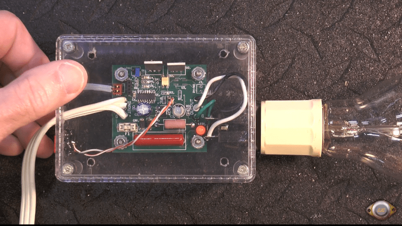
Normally, when you want a low DC voltage from the AC line, you think about using a transformer of some kind. [RCD66] noticed that an AC monitor meter must have some sort of power supply but had no transformers in sight. That led to an exploration of how those work and how you can use them, too. You can watch the work in the video below.
Sensibly, there is a transformer in the test setup — an isolation transformer to make it safe to probe the circuit. But there’s no transformer providing voltage changes. Isolation is important even if you are taking apart something commercial that might be trasformerless.
The circuit is simple enough: it uses a capacitor, a resistor, and a pair of diodes (one of them a zener diode). He uses this basic circuit to drive simple regulators with input and output filter capacitors. We’ve seen many variations on this design over the years.
You can’t draw a lot of power through this arrangement. But sometimes it is all you need. However, this is pretty dangerous, as we’ve discussed before. Be sure you understand exactly what the risks are before you decide to build something like this.


Why does a transformer count as isolation, but not a capacitor? Both are open circuits to DC, and both have the “dangerous” side and the “safe” side directly adjacent to each other in the same package, separated only by a thin layer of insulation. Do transformers tend to fail open while capacitors tend to fail closed, or does the big iron just provide an illusion of safety?
The capacitor only acts as a current limiting impedance. The current flowing through the capacitor is still ground referenced – i.e. the current to the source can return through any grounded conductor – including the human body. This is particularly a problem if the plug gets reversed and the capacitor ends up on the neutral instead of the HOT.
Whereas, the transformer removes the reference to ground and prevents the return current flowing through your body. Note: “Not all transformers”, an “auto” transformer (like nearly all variacs) does not provide ground isolation.
To be honest, I can’t remember the last time I saw a reversible plug. All the ones I’ve seen in the past 10+ years only fit one way.
The main problem is that there’s no shortage of outlets that are wired wrong. I moved into a recently-renovated home and found one. Moved again a couple of years later and found one again. Sometimes, it’s a contractor who gets sloppy doing the hundredth outlet in the home. Other times, it’s the homeowner DIYing a replacement.
I recently had a garbage disposal that was switched off (so it should be unpowered) shooting sparks out of its damaged power cord. A licensed electrician wired that switched outlet.
It’s especially silly when you get a 120V two-wire line cord with a C1 or C7 (reversible, non-polarized) two-prong connector on one end, but still has the polarized blades on the wall plug end.
On appliances where polarization doesn’t matter (i.e., most of them) I often grind off the fatter blade on two-wire cords just to avoid the aggravation.
Anything with switch or fuse only in the hot wire keeps the polarization, of course. As does anything with an edison socket.
All plugs are reversible if you are strong enough.
While most plugs in common use around the world are not reversible, the plugs in use in most of Europe (except the UK, Belgium, France, Italy, and a few others) are reversible. They are, incidentally, also the types that can provide the most power, 16A at 240V.
In some places in Belgium, a 240V socket has 2 live wires of 120V, 180 degrees out of phase. 2x 139V with 120 degree difference is also possible, but I’ve never seen that.
Still, the capacitor will drop a voltage depending on the current, so at zero current, the full voltage is on the other side of the capacitor. If the zener diode fails, you can get the full peak voltage on the output capacitor, but of course that will fail very quickly because it won’t be rated for such a high voltage. Finally, capacitors are much more likely to fail short than a transformer.
The 2-pin Europlug is reversible. The widely-used 3-contact CEE 7/3 socket and CEE 7/4 plug (“schuko”) are reversible. The French CEE 7/5 socket and 7/6 plug are not reversible, but there is no standard for which pole is phase and which neutral. The CEE 7/7 plug is reversible in a German socket, but not in a French one.
But that’s what I’m saying: the capacitor is the isolation.
The main reason is transformer output is not ground referenced.
You could lick a single output from the secondary of a transformer standing in a bath tub. You really shouldn’t of course.
But the capacitor means current is flowing through you cause it’s AC.
If the capacitor is the isolation how do you get current flowing on the other side of it in this circuit? A capcitor only blocks DC, and as PaulB points out in this AC mains circuit “The capacitor only acts as a current limiting impedance”. If this circuit is good for 25mA (through the capactitor) then that’s up to 120V, 25mA that could happily include you in the circuit which is more than enough to be dangerous (I know this is a gross over simplification before anyone points it out).
I recognise I might have just restated the issue. Consider this.
Let’s make a capacitive dropper to output 5Vrms from 230Vrms.
We wanted 23mA, so we need 10k ohm impedence. That meals the capacitors reactance must be 220Ohm.
If the circuit fails with the capacitor lead out you might think I’m isolated it’s fine.
But definitely do not lick that capacitor lead standing in a bathtub!
Many loads do not require a fixed current, and your mains spec has a specified voltage tolerance (and most things will work even when the grid is well out of tolerances). Your capacitor has a pretty wide tolerance as well. You could have pretty wide voltage swings if the voltage is high., the cap is higher than spec, and your load – perhaps involving a µC and some load that it switches on and off. isn’t pulling much.
In short – spec the capacitor to be able to deliver the max needed current, given other tolerances, but under no circumstance expect that your voltage is going to self-regulate because of the load: use some form of voltage regulation, even if it is a Zener.
I have some devices using reactance for a supply, and they’re fused and MOV’d as well – and intended for use inside an enclosure. If you’re doing stuff inside an electrical box with the power on, you should be darned well aware of the risks. Capacitive Reactance is no more dangerous than fiddling around with the input wires to a transformer. If your device has user-interfaces electrical connections (even just serial cable) that themselves are not isolated, then Capacitive Reactance is not for you.
I also use the TI UCC28881 IC for some things (particularly handy for wide DC in voltage) which is a offline switcher – for AC via rectifier. No transformer, though there is an application configuration for flyback use.
The capacitor is a frequency-dependent current source up to a good portion of the input voltage. If you don’t need a constant current or have lots of harmonics and/or spikes on the mains side, a capacitor dropper is a bad idea.
It is often used in LED bulbs, because LEDs are fed with constant current, not voltage.
A capacitor is not a true isolation, it’s intent is to 𝗰𝗼𝘂𝗽𝗹𝗲 AC current and block DC. The current on both leads of the capacitor is the 𝘀𝗮𝗺𝗲 current. The insulator passes a limited amount of current directly through, via an electric field. A charge containing a certain energy builds up on one side and pushes the same charge away from the other side. It’s akin to a voltage-dependent-resistor in series from the input to the output.
Tl;Dr… It’s also akin to getting punched through a sheet of rubber, even though you couldn’t run right through it.
A transformer is a double energy-conversion device using 2 electromagnets that are electrically separate from each other, coupled 𝗼𝗻𝗹𝘆 by magnetism. They could even be physically separate and still work, though less efficient.
Would two capacitors, one on each side, create isolation then? Like in a balanced arrangement.
A capacitor acts more like a wire to alternating current so you can add as many capacitors as you want but it still wont isolate you from AC flowing through you if there’s a current path to earth. The reason a transformer is isolating is that the primary and secondary sides are galvanically isolated, that is the only “connection” between the sides is the magnetic field that’s induced to transfer power. No electrical current flows between the two sides, only a magnetic flux. In comparison, a cap will very much allow current to flow through it if it’s sufficiently high enough frequency (dependent on the capacitance of course).
Switching mode power supplies have transformers and still a safety capacitor is used to connect secondary with primary part. Is it then isolated?
The Y capacitor across the primary and secondary is not really for safety, it’s to allow a path for very high frequency noise from the switching back to the primary side earth. Basically to prevent EMI radiated emissions.
What if the return side has a capacitor in the path too?
Then you have 60V danger.
Many old school device chargers used the capacitor method. If the piece is double insulated it is pretty safe. But there are risks if you are not careful.
The isolation transformer create a floating, not ground referenced voltage on output. In mains socket you have one Hot and one Grounded wire.
If you are grounded and touch Hot wire, you will receive amount of current related to resistance/impedance of your body.
If you touch output from isolation transformer, you will receive only amount current related to isolation resistance/impedance of the transformer.
This not apply if you touch one output wire from transformer with one hand and second output wire with other hand. Then you will receive again the current related to resistance/impedance of your body.
I can’t believe you said that. It’s not DC that kills you!
The amount of AC current at 50 Hz the capacitor passes to the circuit is also there to shock you. You could do capacitor isolation by first converting to low-voltage non-isolated DC, then to high-frequency AC, then through capacitor isolation ( https://www.analog.com/en/resources/design-notes/isolated-power-using-capacitors.html ) and then again to low-voltage isolated DC.
But at that point the transformer starts to feel simple.
Alternatively, if your circuit works with e.g. 100 µW of power, you don’t even need to connect the phase and neutral wires, just put some metal close to them to harvest energy.
One of the stupidest things i’ve done when experimenting with electricity was playing with transformer-less supply design found on internet. It was that time that i had couple of first successful electronic designs nad prototypes behind me and i was geting little bit too confident. With my fingers i was touching 12V rail provided by similar capacitive supply, completely oblivious to the risks involved. Only reason i haven’t received any shock was that i was working at the lab bench that had its mains outlets protected using isolation transformer (effectively making NOT-transformer-less circuit). I’ve only realized my mistake couple days later. Lucky enough, the isolation transformer was installed like week before i’ve been doing the experiment.
Later i’ve started noticing these kinds of supplies being used in cheap chinese LED lightbulbs with exposed pads of individual LEDs and similar cheap stuff… The fact some circuit is providing “safe” voltage across LED does not mean it does not mean there is not an unsafe voltage between that very same LED and something else (lets say your laptop, radiator pipe, or any other circuit…)
Think thrice with this stuff guys.
Yeah I recently needed to disassemble my very old plug-in electric shaver and found a buck converter taking 120/240v to 6v dc to drive the motor. I looked up the part but for the life of me can’t find the number again. The circuit was almost exactly taken from the data sheet. I think it was rated 750ma. No heat sink. Probably 20+ years old and still working fine.
Most LED bulbs nowadays use buck converters or capacitive droppers for power due to cost. Very few still use switch mode supplies with transformers.
A lot of LED bulbs now use a linear regulator with a lot of LEDs in series so the regulator doesn’t have to drop much voltage. They are designed to have a good power factor, which is something you can’t get with a capacitive dropper.
Switching supplies are not necessarily isolated either.
As long as they’re are files and three prong adapters polarity is a crapshoot.
Hackaday, IMO you have liability in recommending experimenting with mains referenced currents. I would say that if you already understand what the risks are, then you don’t need a tutorial showing you how to do this!
Worrying about liability is a creative dead-end.
Sadly, It’s useless to point that out here. The staff and many of the posters have a cavalier attitude in regards to safety. On the bright side, this is far from the most dangerous post I’ve seen. Browse around long enough and you’ll be able to fill out a good chunk of a Darwin Award bingo card.
The anti-safety crowd here is also super sensitive. Many comments pointing out safety or liability issues get dog-piled in quick order.
Maybe they can post a nice disclaimer on the dangerous ones: https://www.youtube.com/watch?v=3G9jjOs1M20
If you want 20kV, just open the secondary on a 4000/1 ct while it is measuring. It makes the big kid crackling sound too. See, you can have fun on the medium voltage side too.
You have not lived until you got a needle burn from a 35KV color display CRT into your hand!
Very common design method for mass low materials cost products for some industries such as HVAC. The capacitor is the primary limiting element often feeding a zener stack to provide multiple voltages. This can power any thing from simple basic sensor circuit to to a small micro like a PIC. The entire circuit is electrically hot relative to the mains. These are typically potted with a relay providing the control output and galvanic isolation. Selecting a capacitor of appropriate value can be a little bit of a task. They are often not specified for AC do you have to pick one with a sufficient DC rating for peak mains voltage plus margin.
Getting UL or CE electrical safety compliance normally requires surge testing to far higher voltages than the nominal mains voltage. In EMC filters capacitor sused across the mains are normally a self healing poly something capacitor rated to some safety rating. These are known as X capacitors. This is the grade from a safety perspective that should be used.
The capacitor values at least in mains power monitors, used to derive the lower DC voltage control power. The “kilawatt” brand are in the region of 270nF to 330nF. These have been known to fail when capacitor degrades due to mains surges. The self healing propery reduces the capactance slightly during each surge
Note that Neutral is considerd a mains conductor regardless of the fact it maybe close to ground or protective earth potential.
Read UL61010 or EN61010 typically derived from IEC61010. Older versions of these standards can be found outdated but still relevant copies online somewhere.
See the definition of SELV safe electric low voltage online. Any isolation sysyem needs to be designed for possible mains surges. These voltages often very fast can be upto 500V or more in residential environments on top of the mains although of short duration say 10s of microseconds.
Look into mains surge testing for product design it is quite dangerous fun when testing in industrial certification labs.
Simple advice DO NOT expose any person or pet to the low voltage DC or AC created from non transformer generated DC from any mains derived Hazardous eg mains voltage.
Most of this has been learnt the hard way by personal shocks from primary or grade school age. I have since designed electrical products commercialy and been involved in compliance testing and approval.
Any DC control voltage derived from a capacitor straight from mains should be isolated as if it were mains potential !!
The main thing here is this cheap way and it’s able to get trashed along with your gear when any bad line spike happens. Cap droppers readily let a spike pass. Needs a big zener and so much protection that is it worth it?
A couple other thing to note: Capacitive Droppers also have a terrible power factor, so besides being dangerous they are also terrible for efficiency. If they don’t use Y Caps and other safeties they also have a much higher catastrophic failure rate as far as shorting across the capacitor.
When I was a teenager I had an old AC-DC tube-based AM radio that was designed to hang over the headboard of the bed so you could listen to it before you went to sleep. I was already interested in electronics at that point so I knew to be very careful with it, but those old radios were notorious widow makers.
So a capacitive voltage divider? Basically how your led light bulbs work
But lots of flickering, expensive one use a flyback type circuit or zvs, to keep efficiency and you can’t see a 20khz flicker
You can also do the same and get a voltage multplier
Catch is that the output is pulsed dc with a lot of ripple,
But even pulsed dc can still drive a transformer
Technically it’s ac, but doesn’t center around 0v center point of it is half the total output voltage
To be safe a mains rated X or Y rated capacitor is needed. Plus a fuseable series resistor.
I have also used similar circuit to monitor RF transmitter by using a few mW to drive an LED from the Watts of RF. Can be used up to at least 1GHz, in which case series capacitance needs to be about 0.5pF !