Electrical Steel: The Material At The Heart Of The Grid

When thoughts turn to the modernization and decarbonization of our transportation infrastructure, one imagines it to be dominated by exotic materials. EV motors and wind turbine generators need magnets made with rare earth metals (which turn out to be not all that rare), batteries for cars and grid storage need lithium and cobalt, and of course an abundance of extremely pure silicon is needed to provide the computational power that makes everything work. Throw in healthy pinches of graphene, carbon fiber composites and ceramics, and minerals like molybdenum, and the recipe starts looking pretty exotic.

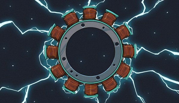
As necessary as they are, all these exotic materials are worthless without a foundation of more familiar materials, ones that humans have been extracting and exploiting for eons. Mine all the neodymium you want, but without materials like copper for motor and generator windings, your EV is going nowhere and wind turbines are just big lawn ornaments. But just as important is iron, specifically as the alloy steel, which not only forms the structural elements of nearly everything mechanical but also appears in the stators and rotors of motors and generators, as well as the cores of the giant transformers that the electrical grid is built from.

Not just any steel will do for electrical use, though; special formulations, collectively known as electrical steel, are needed to build these electromagnetic devices. Electrical steel is simple in concept but complex in detail, and has become absolutely vital to the functioning of modern society. So it pays to take a look at what electrical steel is and how it works, and why we’re going nowhere without it.

Continue reading “Electrical Steel: The Material At The Heart Of The Grid”

Parts We Miss: The Mains Transformer

About two decades ago there was a quiet revolution in electronics which went unnoticed by many, but which overturned a hundred years of accepted practice. You’d have noticed it if you had a mobile phone, the charger for your Nokia dumbphone around the year 2000 would have been a weighty device, while the one for your feature phone five years later would have been about the same size but relatively light as a feather. The electronics industry abandoned the mains transformer from their wall wart power supplies and other places in favour of the much lighter and efficient switch mode power supply. Small mains transformers which had been ubiquitous in electronics projects for many years, slowly followed suit.

Coils Of Wire, Doing Magic With Electrons

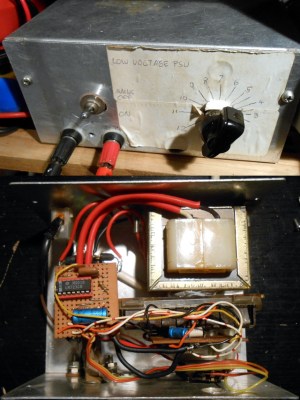
Inside and outside views of Jenny Lists's home made linear power supply from about 1990
This was a state of the art project for a future Hackaday scribe back in 1990.

A transformer works through transferring alternating electrical current into magnetic flux by means of a coil of wire, and then converting the flux back to electric current in a second coil. The flux is channeled through a ferromagnetic transformer core made of iron in the case of a mains transformer, and the ratio of input voltage to output voltage is the same as the turns ratio between the two. They provide a safe isolation between their two sides, and in the case of a mains transformer they often have a voltage regulating function as their core material is selected to saturate should the input voltage become too high. The efficiency of a transformer depends on a range of factors including its core material and the frequency of operation, with transformer size decreasing with frequency as efficiency increases.

When energy efficiency rules were introduced over recent decades they would signal the demise of the mains transformer, as the greater efficiency of a switch-mode supply became the easiest way to achieve the energy savings. In a sense the mains transformer never went away, as it morphed into the small ferrite-cored part running at a higher frequency in the switch-mode circuitry, but it’s fair to say that the iron-cored transformers of old are now a rare sight. Does this matter? It’s time to unpack some of the issues surrounding a small power supply. Continue reading “Parts We Miss: The Mains Transformer”

Flipped Transformer Powers Budget-Friendly Vacuum Tube Amp

If you’ve ever wondered why something like a radio or a TV could command a hefty fraction of a family’s yearly income back in the day, a likely culprit is the collection of power transformers needed to run all those hungry, hungry tubes. Now fast-forward a half-century or more, and affordable, good-quality power transformers are still a problem, and often where modern retro projects go to die. Luckily, [Terry] at D-Lab Electronics has a few suggestions onĀ budget-friendly transformers, and even shows off a nice three-tube audio amp using them.

The reason transformers were and still are expensive has a lot to do with materials. To build a transformer with enough oomph to run everything takes a lot of iron and copper, the latter of which is notoriously expensive these days. There’s also the problem of market demand; with most modern electronics favoring switched-mode power supplies, there’s just not a huge market for these big lunkers anymore, making for a supply and demand equation that’s not in the hobbyist’s favor.

Rather than shelling out $70 or more for something like a Hammond 269EX, [Terry]’s suggestion is to modify an isolation transformer, specifically the Triad N-68X. The transformer has a primary designed for either 120 or 230 volts, and a secondary that delivers 115 volts. Turn that around, though, and you can get 230 volts out from the typical North American mains supply — good enough for the plate supply on the little amp shown. That leaves the problem of powering the heaters for the tubes, which is usually the job of a second 6- or 12-volt winding on a power transformer. Luckily, the surplus market has a lot of little 6.3-volt transformers available on the cheap, so that shouldn’t be a problem.

We have to say that the amp [Terry] put these transformers to work in sounds pretty amazing — not a hint of hum. Good work, we say, but we hope he has a plan in case the vacuum tube shortage gets any worse.

Continue reading “Flipped Transformer Powers Budget-Friendly Vacuum Tube Amp”

AC-DC Converter Is Reliable, Safe, And Efficient

When first starting an electronics project, it’s not uncommon to dive right in to getting the core parts of the project working. Breadboarding the project usually involves working with a benchtop power supply of some sort, but when it comes to finalizing the project the actual power supply is often glossed over. It’s not a glamorous part of a project or the part most of us want to be working with, but it’s critical to making sure projects don’t turn up with mysterious issues in the future. We can look to some others’ work to simplify this part of our projects, though, like this power supply from [hesam.moshiri].

The power supply is designed around a switch-mode topology known as a flyback converter. Flyback converters work by storing electrical energy in the magnetic field of a transformer when it is switched on, and then delivering that energy to the circuit when it is switched off. By manipulating the switching frequency and turns ratios of the transformer, the circuit can have an arbitrary output voltage. In this case, it is designed to take 220V AC and convert it to 8V DC. It uses a simplified controller chip to decrease complexity and parts count, maintains galvanic isolation for safety, and is built to be as stable as possible within its 24W power limitation to eliminate any potential issues downstream.

For anyone trying to track down electrical gremlins in a project, it’s not a bad idea to take a long look at the power supply first. Any noise or unwanted behavior here is likely to cause effects especially in projects involving sensors, ADC or DAC, or other low-voltage or sensitive components. The schematic and bill of materials are available for this one as well, so anyone’s next project could use this and even make slight adjustments to change the output voltage if needed. And, if this is your first introduction to switched-mode power supplies, check out this in-depth look at the similar buck converter circuit to better understand what’s going on behind the scenes on these devices.

Continue reading “AC-DC Converter Is Reliable, Safe, And Efficient”

Don’t Let The Baluns Float Over Your Head

Most ham radio operators will build an antenna of some sort when they first start listening or transmitting, whether it’s a simple dipole, a beam antenna like a Yagi, or even just a random wire vertical antenna. All of these will need to be connected feedline of some sort, and in the likely event you reach for some 50-ohm coax cable you’ll also need a balun to reduce noise or unwanted radiation. Don’t be afraid of extra expenses when getting into this hobby, though, as [W6NBC] demonstrates how to construct an “ugly balun” out of the coax wire itself (PDF).

The main purpose of a balun, a contraction of “balanced-unbalanced” is to convert an unbalanced transmission line to a balanced one. However, as [W6NBC] explains, this explanation obscures much of what baluns are actually doing. In reality, they take a three-wire system (the coax) and convert it to a two-wire system (the antenna), which keeps all of the electrical noise and current on the shield wire of the coax from interfering with the desirable RF on the interior of the coax.

This might seem somewhat confusing on the surface, as coax wires only have a center conductor and a shield wire, but thanks to the skin effect which drives currents to the outside of the conductor, the shield wire effectively becomes two conductors when taking into account its inner and outer surfaces. At these high frequencies the balun is acting as a choke which keeps these two high-frequency conductors separate from one another, and keeps all the noise on the outside of the shield wire and out of the transmitter or receiver.

Granted, the world of high-frequency radio circuits can get quite complex and counter-intuitive and, as we’ve shown before, can behave quite unexpectedly when compared to DC or even mains-frequency AC. But a proper understanding of baluns and other types of transformers and the ways they interact with RF can be a powerful tool to have. We’eve even seen other hams use specialty transformers like these to make antennas out of random lengths and shapes of wire.

Continue reading “Don’t Let The Baluns Float Over Your Head”

Your Multimeter Might Be Lying To You

Multimeters are indispensable tools when working on electronics. It’s almost impossible to build any but the most basic of circuits without one to test and troubleshoot potential issues, and they make possible a large array of measurement capabilities that are not easily performed otherwise. But when things start getting a little more complex it’s important to know their limitations, specifically around what they will tell you about circuits designed for high frequency. [watersstanton] explains in this video while troubleshooting an antenna circuit for ham radio.

The issue that often confuses people new to radio or other high-frequency projects revolves around the continuity testing function found on most multimeters. While useful for testing wiring and making sure connections are solid, they typically only test using DC. When applying AC to the same circuits, inductors start to offer higher impedance and capacitors lower impedance, up to the point that they become open and short circuits respectively. The same happens to transformers, but can also most antennas which often look like short circuits to ground at DC but can offer just enough impedance at their designed frequency to efficiently resonate and send out radio waves.

This can give some confusing readings, such as when testing to make sure that a RF connector isn’t shorted out after soldering it to a coaxial cable for example. If an antenna is connected to the other side, it’s possible a meter will show a short at DC which might indicate a flaw in the soldering of the connector if the user isn’t mindful of this high-frequency impedance. We actually featured a unique antenna design recently that’s built entirely on a PCB that would show this DC short but behaves surprisingly well when sending out WiFi signals.

Continue reading “Your Multimeter Might Be Lying To You”

Not A Pot, Not An Encoder: Exploring Synchros For Rotational Sensing

We’re all familiar with getting feedback from a rotating shaft, for which we usually employ a potentiometer or encoder. But there’s another device that, while less well-known, has some advantages that just might make it worth figuring out how to include it in hobbyist projects: the synchro.

If you’ve never heard of a synchro, don’t feel bad; as [Glen Akins] explains, it’s an expensive bit of kit most commonly found in avionics gear. It’s in effect a set of coaxial transformers with a three-phase stator coil and a single-phase rotor. When excited by an AC reference voltage, the voltage induced on the rotor coil is proportional to the cosine of the angle between the rotor and stator. It seems simple enough, but the reality is that synchros present some interfacing challenges.

[Glen] chose a surplus altitude alert indicator for his experiments, a formidable-looking piece of avionics. Also formidable was the bench full of electronics needed to drive and decode the synchro inside it — a 26-volt 400-Hz AC reference voltage generator, an industrial data acquisition module to digitize the synchro output, and an ESP32 dev board with a little OLED display to show the results. And those are impressive; as seen in the video below, the whole setup is capable of detecting tenth-of-a-degree differences in rotation.

The blog post has a wealth of detail on using synchros, as does this Retrotechtacular piece from our own [Al Williams]. Are they practical for general hobbyist use? Probably not, but it’s still cool to see them put to use.

Continue reading “Not A Pot, Not An Encoder: Exploring Synchros For Rotational Sensing”