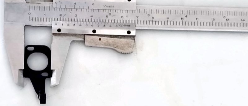
We’ve certainly seen people take a photo of a part, bring it into CAD, and then scale it until some dimension on the screen is the same as a known dimension of the part. We like what [Scale Addition] shows in the video below. In addition to a picture of the part, he also takes a picture of a vernier caliper gripping the part. Now your scale is built into the picture, and you can edit out the caliper later.
He uses SketchUp, but this would work on any software that can import an image. Given the image with the correct scale, it is usually trivial to sketch over the image or even use an automatic tracing function. You still need some measurements, of course. The part in question has a vertical portion that doesn’t show up in a flat photograph. We’ve had good luck using a flatbed scanner before, and there’s no reason you couldn’t scan a part with a caliper for scale.
This is one case where a digital caliper probably isn’t as handy as an old-school one. But it would be possible to do the same trick with any measurement device. You could even take your picture on a grid of known dimensions. This would also allow you to check that the distances at the top and bottom are the same as the distances on the right and left.
Of course, you can get 3D scanners, but they have their own challenges.


When I need to copy a part that may be in a location away from my workbench, I just photo it with a £1 coin for scale (other currencies are available).
Just looked at the Royal mint website – what a weird collection of diameters! https://www.royalmint.com/discover/uk-coins/coin-design-and-specifications/
Interesting approach, but how do you adjust for inflation?
I don’t hand these out often, but you’ve earned +1 Internet points with that comment!
That was in fact golden.
I often just put a ruler beside it and try and make sure the camera is as parallel to the surface as possible and as far away as reasonable, that way the X and Y dimensions are as close as possible and you only need one axis for scale.
Why don’t we have caliber paper? A series of known points with a QR code and an app that turns it into a scaled drawing.
We have, its called ‘shaper trace’.
A round coin is an excellent scale indicator. I’ve used one (Australian 20c coin) many times when photographing WWII military vehicles I intend to produce a scale model of, or markings on these vehicles I want to produce a decal of.
Being round, a construction line can be drawn across the coin’s diameter in the photo that is always parallel to the focal plane of the camera, which is needed when scaling panels that are not perfectly perpendicular to the camera.
While you can always find a parallel line to the camera’s focal plane from a round object, I doubt you can actually find it with any accuracy in practice.
The coin will be stretched and squished by the lens distortion and the perspective error, so you kinda have to guess what diameter line actually lines up with the image plane. You can measure the coin crosswise to find out how much the photograph is distorted somewhere close to the coin, but that doesn’t apply to all parts of the image.
Professional photographer here, well retired now, but anyway:
The super duper easy way to make sure that the camera and the surface are parallel to each other is to place a mirror on the surface, and adjust the position of the camera so the reflected image of tha lens is in the center of the frame. I keep a small mirror in my camera bag just for that. Works great with a phone camera in the library too.
I suppose a paper ruler stuck to one edge would make it even more handy.
By frame, I mean the image in the camera if that was not clear.
We used the same trick on a much bigger scale useing a known grid to design and fit grill guards to semi trucks so it even at a very large size
It’s already built into the picture because you know the scanner’s linear resolution. It’s pixels to inches directly, so you can measure it in any image editing software.
This trick with the calipers applies to photographs where the focal distance is unknown. But, if you set up your camera at a known distance and zoom it all the way in, you can pretty much make the same direct conversion of pixels to inches on the resulting image after measuring it once.
Also, photographing your calipers with the part in between does not give you accurate measurements because of lens distortion (barrel distortion). To reduce this effect, and make parallel lines parallel, you have to take the photograph with a small aperture using a long lens – in other words you need to zoom in from a distance.
The example in the video with a camera phone (no real zoom) taken from mere inches away, and not controlling for having the image sensor parallel to the desk or the surface of the part, will give you wildly varying results. Parts that are straight or surfaces that are parallel will appear tapered or diamond shaped etc.
If you model the part directly off of the photo like that, you basically have to guess what the varying distances are really supposed to be, which means it’d be faster to skip the photographing and just eyeball it directly off the actual part and the caliper readings.
Relying on sensor data from the scanner is often not reliable because of image scaling (which you may or may not have control over). You need to know the magnification of the system, and the easiest way to do this is to scan something of a known length.
Scanners have corrected optics to account distortion, though you should only assume the best accuracy for surfaces that lie flat against the scanner bed. Additionally for small parts near the center of the FOV the distortion will be minimal. Either way, this approach is often more than good enough.
“You need to know the magnification of the system, and the easiest way to do this is to scan something of a known length.”
Like, oh I dunno, the scale on a set of calipers?
Haha, that’s what I was hinting at, especially given this statement:
“It’s already built into the picture because you know the scanner’s linear resolution. It’s pixels to inches directly, so you can measure it in any image editing software.”
If I scan at 300dpi I have all the reference I need. 300 pixels = 1 inch. Which can be trivially verified by printing the scanned image at 300dpi and placing the part onto the print, they’ll match.
You only ever need to check it once and then you know it.
The important part for a technique like this is that the part is in focus and minimally distorted so the tracing into CAD is suitably accurate, what happens to the measuring device distortion wise at the edge of the frame really isn’t important at all until it gets too blurred to actually read the scale.
The measurement shouldn’t really change even with distortion. As while the distortion might make it slightly harder to read the scale it is distorted pretty evenly with the moving line and the static basically touching the distortion difference between them makes little difference – either at that interface between lines these two or those two line up best – so which one is the least stair stepped. You’d probably find most folks can get a more accurate measure on the finer verniers in the picture than with their own unassisted eyeballs as you can easily zoom in on the picture! Also the less precise verniers and calipers in general are not really “accurate” measuring devices anyway – good enough for the task perhaps, especially if its woodwork, but still all those long levers to flex and twist…
The distortion isn’t limited to the edges of the image, especially if you fail to line the object flat with the sensor plane.
Yes they would. Go ahead and photograph a graph paper from 12 inches away with your cellphone camera, then pick a random square and use your favorite image editing software to measure the diagonals to see whether it is actually square in the picture. Check multiple – they’ll all be different.
I’m talking about reading the caliper to get dimensions as done here – you put the part in the minimally distorted part of the image, which is usually a pretty big circle in the centre that will be more than good enough, at least if calipers are accurate enough to measure with in the first place… The distortion just flat out doesn’t matter being only bad well away from the part, and not interfering with the ability to read the measuring device that is setting a dimension in your CAD model.
But you can do that by simply looking at it.
Again, I encourage you to actually try it out and see for yourself. Take a picture of a graph paper with your phone camera and measure how square the squares are in the image.
@Dude It really really doesn’t matter (though I’d not use a phone camera by choice) any camera taking a photo of a small part with a little care in the setup will be accurate enough with the part in the centre of the image if calipers where accurate enough to measure it anyway.
Calipers even really good ones are not reliable repeatable measuring devices with how much bend they can have in them as you clamp on the part. Often only really only go to the nearest 0.1mm reliably, though with care and a good set you should be able to do better they are still not the micrometer and surface plates of measuring – So the distortions in the middle of your lens are in the same sort of ballpark to likely an order of magnitude less than the accuracy as your measuring tool – making it irrelevant. Its errors in the tolerance window you are measuring to, at least if you put any effort into taking that picture.
Yep. This right here. I bought an old flatbed scanner to battle the issue for flat-ish objects.
My phone’s camera can zoom in far more than I need it to for reducing parallax. It used to be true that phones didn’t have any real zoom to speak of. That hasn’t been the case for several years.
Galaxy Ultra series of phones has a very respectable optical zoom.
They don’t. They just crop and resample the image (“digital zoom”), or have a second or third camera with the focal distance fixed long, and then they blend the images in software. The multi-camera version presents a problem, because the images that are blended together aren’t captured from the same vantage point, so you get weird parallax errors depending on what the software decides to do.
I have not watched the video as I have been following this method myself for years. In Fusion when you bring in the picture to sketch you have an option to calibrate the dimensions. You need a known distance there. If you have a grid or a scale or a coin which you can easily click and enter the distance Fusion will take care of rest of the image. Unless you are taking the image from very abtuse angle the image dimensions should be same across entire image pane.
But then you have to write down the distance so you don’t forget. Also, your camera needs to have a focal plane marker so you know what distance to measure from, and you need to make sure your lens’s nominal focal length is accurate. I doubt how accurate the nominal endpoints of a zoom lens are. And there is focus breathing. https://photo.stackexchange.com/questions/91601/are-lenses-marked-with-the-true-focal-length
You could easily verify and finely calibrate this measurement by scanning your calipers once, and then you’d just need to toss a part on the scanner and apply the conversion. No need to fiddle with calipers after that.
You could look up the linear resolution, but I wouldn’t trust that figure to be sub-millimeter accurate.
Exactly this. Just scan at 1000dpi and scale is super easy.
I usually lay the object flat on a piece of 5mm grid paper.
A limitation is parallax error because of the thickness of the object. Punching a hole in the paper and lifting it so it’s sort of parallel with the top surface of the object helps.
It also helps if you have a physically big distance between the camera and your object. Then use the zoom function at maximum level to get more usable pixels.
Another trick is to use your calipers to measure a few critical dimensions, and then make a simple sketch and write those dimensions on the grid paper too before you make the photograph.
But normally I have the objects, camera, calipers and my PC all within easy reach. When away, putting anything in the picture that gives a size reference helps. This can be a coin or a pen, or a hand or foot, or whatever other object with known size is available. Results are always best if the reference object is similar in size as the object to be digitized, and also at the same distance from the camera.
What if you take two photos: one with the part and another with the grid paper at a set distance, then superimpose the two. You can intersect the grid at any depth through the object.
Or, if you wanna go one-shot with it, use a half-mirror in a box to overlay an image of the grid on the object. Again, where you place the object relative to the mirror makes the grid intersect the object at a different depth.
Bad Idea. Differences in distance to the camera will get you different scale factors. Using a mirror and box also sound complicated, with no added benefit.
If you want to go fancy, you can go in the direction of “structured light” or other 3D scanner techniques (Photogrammetry is also fun) But that’s all beyond the scope of this article.
Well obviously you wouldn’t be holding the camera in your hand.
I’ve done this by placing a ruler next to the object.
I did something like this the other day.
A couple of years ago, I wrote a blog post about a sewing machine table. It had close up photos of the hinges and other things.
Someone saw those photos, and posted a comment asking for a dimensioned sketch of the hinge. They had an identical cabinet that was missing the hinges.
I no longer had that cabinet – it belonged to someone else and I couldn’t go borrow it again.
In looking at the photos, I saw that there was a piece of brass tube in the picture. I’d used the tube as a tool to remove an escutcheon from the cabinet.
The tube is exactly 5mm in diameter.
I pulled the photo into Inkscape, scaled the picture so that the tube was exactly 5mm wide, then traced the hinge. Presto: properly scaled drawing of a part I no longer had to hand.
I do this often but flatbed scanners still have parallax and it’s sometimes hard to determine the exact edge due to the lighting.
I think it’s possible to get better results with a good camera set up and a few tricks (like using a mirror to ensure the lens is perfectly parallel, adjusting the incident light angle to sharpen the edges).
Maybe I should make a video on the topic!
I’d watch it
I don’t fully understand what this hack is for. Is it in case you forgot to measure something? I keep calipers and my part near me while I do CAD.
It’s basically measuring everything at once, so you can lay your lines down to the picture rather than measuring everything in separate. If done right, it saves time, if done wrong it creates wonky parts that never measure up to the original.
He uses SketchUp
HOW?? How in 2025 do people still use that garbage software? I learned to do CAD on it but then I found the world of solid modeling, parametric modeling, feature-based modeling, etc and now SketchUp is a joke to me. I used to get so frustrated at the simplest things like changing a hole size or position. Hard to do without sketches or feature-based sketches.
WHat would you reccomend I realy like Rhino but its $$$$$$
LOL!
I was thinking the same thing.
Although I have to admit, I used it for a while. Until I started doing 3D printing. The “models” that SketchUp create will give slicer fits.
My buddy uses SketchUp almost exclusively. It’s what he started with so it’s his fastest easiest tool. “I’m just trying to slam out a print, I don’t wanna learn a new tool”.
Similar here, I use two pieces of 3d CAD software, one that’s available (for free to almost anyone who cares to find it and register) from my employer and another which is free from a major UK parts distributor, of the two my favouirite is the far simpler parts distie one because I can knock out working designs in far less time.
Sketchup is about doing complex things the simple way, being the only way. You just have to get good at it.
All the other software is about learning to use very specific tools to achieve very specific tasks, which means there’s a learning curve and limits to what you can do if your task doesn’t fall exactly within the tools you’re using.
It’s like, you can draw any shape with a pencil – you just have to know how to draw. You can also draw any shape with a stencil – you just have to have exactly the right stencil. Sketchup is like the pencil – you can do pretty much everything you can imagine, but you got to do it the hard way.
HAHA! Up until last year when I finally took a Fusion class, I had been using Microsoft Visio for all my CAD drawings. I literally have 2 decades worth of cable assembly drawings, laser cutting templates, mechanical drawings, etc, etc. A good friend of me hounded me routinely for the past 15 years about it.
How is photogrammetry coming along for this? It’s always been my favorite since it just takes lots of pictures and some processing time to get what should be a very accurate 3D model.
Is it getting easier to get good results?
The comments here seem to miss a key point: It is a measurement technique that works. It is optimal? not always, but you can’t always bring the part back to the lab, put it on the digital control, 1micron resolution, 75mm field telecentric lens equipped measurement centre. This is a nice way to get decent precision without worrying about keeping track of what measure goes with what feature.
I have done this any number of times in the field, where the part can’t come out until the replacement is made, or the feature is otherwise inaccessible, or the part is too large to carry back to the CAD station. Back in the day (I’m aging myself) a Polaroid camera was mandatory kit for field work, in part for this type of task. I much prefer digital cams. We have now reached the point with cell phones where all of the AI image processing crap and lack of raw data has made them less useful in some cases. I have gone back to my old Canon after a few cases where the feature I needed got processed into uselessness by jpeg conversion and uncontrollable features on the phone.
Indeed, unless the phone gives access to the raw take from the sensors I’m not interested in using it, even though its got better over the years the AI still goes bonkers from time to time – for instance a buddy had a few photos of taking his nipper and parents to a motor museum that happens to have a FAB 1 from the modern Thunderbirds movie and at those dual front wheels in the background a shot it is just garbled awfully, as it knows its a car and is trying to turn two wheels into one I assume…
I don’t mind having the automatic and magic processing modes available at all, making getting that quick low effort picture for whatever reason easy, pulling the focus to something at least close automatically etc… But when you actually want a good result you want something rather more unprocessed if not the actually RAW, so the device really should store that – can always process it afterwards if you want…
So basically he’s using the caliper as a high precision banana.
The trickiest part of this is when they have to calibrate those calipers at the factory w.o squashing the bananas.
I wonder what level of precision is realistically achievable if you only use various random bananas (or even the same one but you have to deal with it becoming brown and squishy and shriveled so there is measurement drift)… Could you build a decent sailboat? A house? Could you average several bananas at all time to increase repeatability? How sophisticated could you get?
You could take a photograph of the banana, and the place copies of that around.
i use this kind of approach when i don’t have any choice, like discerning gross geometry from an outdoor photo. but i don’t like it specifically for 3d printing because the image is never quite in the same plane as the object — neither orthogonal nor centered. so there’s perspective distortion. in practice for me at least it turns squirrelly and imprecise. plus, it’s almost always easy for me to measure the device directly with calipers, especially for the example object here.
Buy a cutting mat. Put cutting mat on your bench. Put thing on cutting mat. Take picture.