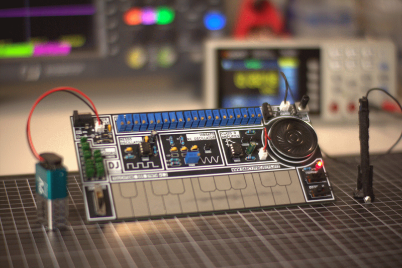
For all that “should have used a 555” is a bit of a meme around here, there’s some truth to it. The humble 555 is a wonderful tool in the right hands. That’s why it’s wonderful to see this all-analog stylus synth project by EE student [DarcyJ] bringing the 555 out for the new generation.
The project is heavily inspired by the vintage stylophone, but has some neat tweaks. A capacitor bank means multiple octaves are available, and using a ladder of trim pots instead of fixed resistors makes every note tunable. [Darcy] of course included the vibrato function of the original, but no, he did not use a 555 for that, too. He used an RC oscillator. He put a trim pot on that, too, to control the depth of vibrato, which we don’t recall seeing on the original stylophone.
The writeup is very high quality and could be recommended to anyone just getting started in analog (or analogue) electronics– not only does [Darcy] explain his design process, he also shows his pratfalls and mistakes, like in the various revisions he went through before discovering the push-pull amplifier that ultimately powers the speaker.
Since each circuit is separately laid out and indicated on the PCB [Darcy] designed in KiCad for this project. Between that and everything being thru-hole, it seems like [Darcy] has the makings of a lovely training kit. If you’re interested in rolling your own, the files are on GitHub under a CERN-OHL-S v2 license, and don’t forget to check out the demo video embedded below to hear it in action.
Of course, making music on the 555 is hardly a new hack. We’ve seen everything from accordions to paper-tape player pianos to squonkboxes over the years. Got another use for the 555? Let us know about it, in the inevitable shill for our tip line you all knew was coming.


“[Darcy] of course included the vibrato function of the original, and yes, he used a 555 for that, too.”
The only use of 555 is for the main oscillator. The vibrato is driven by an RC oscillator, not another 555.
Should have used a 556.
[https://www.ti.com/lit/ds/symlink/na556.pdf]
I have no idea what caused that brain fart, and no excuse. It’s not only in the documentation, it’s silkscreened right there on the board!
I’ve fixed it.
Should have used a CEM3340 or that type of synth chip then you would have sine and other waveforms instead of just square. Nonetheless a good project. For once a simple musical project that can be tuned properly ET or mean. No space between the sharps makes it hard to do a chromatic glissando, should be equal width at the rear.
Not that easy, because the CEM3340 requires +/-12 V supply… Would be a different project actually.
These chips are hard to get in small quantities, even the clones. The few stores that sell them still have relatively expensive shipping compared to the item. They’re doing their best, but still there’s a threshold not crossed.
If you, yes you reading this, have enough money, please buy a batch of synth chips and bring them to your local hacker space, ham radio club, etc, and let people take some if they commit to at least trying to get it working on a breadboard. You can make parts available to the people who will experiment with them. Otherwise we’ll be stuck with jellybean parts.
Would have been a totally project. I think the goal here was to put a 555 to good use, IMHO
TouchTone555 is a clever name.
Thanks for the link to the “sqonkbox” in the article.