Cable harness design is a critical yet often overlooked aspect of electronics design, just as essential as PCB design. While numerous software options exist for PCB design, cable harness design tools are far less common, making innovative solutions like Splice CAD particularly exciting. We’re excited to share this new tool submitted by Splice CAD.
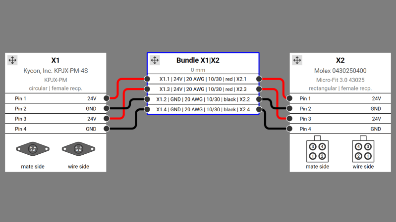
Splice CAD is a browser-based tool for designing cable assemblies. It allows users to create custom connectors and cables while providing access to a growing library of predefined components. The intuitive node editor enables users to drag and connect connector pins to cable wires and other pinned connectors. Those familiar with wire harnesses know the complexity of capturing all necessary details, so having a tool that consolidates these properties is incredibly powerful.
Among the wire harness tools we’ve featured, Splice CAD stands out as the most feature-rich to date. Users can define custom connectors with minimal details, such as the number of pins, or include comprehensive information like photos and datasheets. Additionally, by entering a manufacturer’s part number, the tool automatically retrieves relevant data from various distributor websites. The cable definition tool is equally robust, enabling users to specify even the most obscure cables.
Once connectors, cables, and connections are defined, users can export their designs in multiple formats, including SVG or PDF for layouts, and CSV for a detailed bill of materials. Designs can also be shared via a read-only link on the Splice CAD website, allowing others to view the harness and its associated details. For those unsure if the tool meets their needs, Splice CAD offers full functionality without requiring an account, though signing in (which is free) is necessary to save or export designs. The tool also includes a version control system, ideal for tracking design changes over time. Explore our other cable harness articles for more tips and tricks on building intricate wire assemblies.


This is neat, but really this belongs inside kicad, as an alternative to the board layout process.
A PCB has a schematic/netlist, and components, and physical attributes like trace size and hole positions.
A harness has a schematic/netlist, and components, and physical attributes like wire size and heatshrink details.
If you start with eeschema and then export a netlist to pcbnew, you should be able to just as easily start with eeschema and export a netlist to, let’s call it, harnessnew.
This gets extra cool when you realize that a multi-sheet schematic could have some sheets that represent boards, and some sheets that represent harnesses, and you could trace connections through the complete assembly. It’s really just a special board with the insulating parts made of PVC instead of FR4.
Hi – thanks for your feedback!
Yes, the disconnect between PCB design and the required cable assemblies is a headache and not something we currently address.
In lieu of a CAD-specific implementation, what do you think about the utility of the option to upload Gerbers and a PCB BOM to the platform and extract mating connectors and signals to generate all but the terminating connectors for the assemblies? Not a complete integration, but a step in reducing amount or replicative work.
Hi Matt – thank you for the very kind write-up!
This project is in the nascent stages and I’m sure many reading this will have ideas for improvement/extension – if anyone would like to reach out directly, my email is info@splice-cad.com. – Danny
The idea is great – but implementation I give it a thumbs down.
I’ve designed and built wiring harnesses, in real engineering and manufacturing environments. I’ve outsourced to commercial cable assy manufacturers too.
The “scientific” programmers for this project need to actually build some cable harnesses. Get some hands-on experience to know what users actually need instead of this. I can give 100 examples of what is missing, why it’s too hard for people on the shop floor to follow, one conductor in a harness a bit longer than the others seems to blow its mind. Where are the tie-wraps, cable sheaths, what crimping tool is required oh it’s soldered, real pics of the connector or ends, our company’s part numbers etc. etc. The push to the Supply Chain, BoM is premature. You don’t know if we need a spool of wire ordered or a few pins got lost on the floor.
I see these theoretical CAD programs come out and not catch on because they were poorly designed and make it far too complicated compared to the old tried and true ways of doing it. You can’t really dedicate staff to this program alone.
Hi Kelly!
Thanks for the feedback!
I know we can’t catch all of the design nuances in our current structure – would something like the ability to add a note to the harness for tie-wraps, a sheath call out, etc. address some of your needs?
Danny, just some suggestions.
If a connector housing is say female, don’t show the male one (people get mixed up) and wire side is only for pin insertion but testing needs to view the other (mate) side. Where are the housing ears and latch etc.
You don’t realize assembling a cable, and the labour doing it requires no knowledge of electronics and signals. These people are simple, imagine doing this day in and day out. How about real pictures of the connector ends, not tiny too small to read ones i.e. Kycon is hilariously small to read pin #’s. Why do you show pin numbering with negative contrast or not, what does that mean. How do you do a flying lead with a ring crimp connector on the end?
I sort of expect an object-oriented breakdown so anything can be put on the end of a wire, not just the chosen connector housing. And where are those pins and p/n and BoM add? Do the pins fit the wire size? Should be automatic check. What crimping tool?
It’s plastered with wire details but not really. The insulation type and voltage rating are very important. 1/3 of the screen is wire details.
You could add a pegboard designer feature. Support wire labels. I could go on but…
I would be very scared to let this S/W into inventory control- Does it know I have 10 harnesses to build today and do I have enough wire in stock, will it show we’re out, will it simply re-order for the day, does it keep minimums? When you run out of a wire, it’s a bad day everything is on hold until a panick shipment comes in, or somebody approves using alternates.
Thank you for the suggestions, mm! I have some questions to help me understand below –
“If a connector housing is say female, don’t show the male one (people get mixed up) and wire side is only for pin insertion but testing needs to view the other (mate) side. Where are the housing ears and latch etc.”
Apologies for the confusion here – can you clarify where you’re seeing a male connector where it should be female? Our Mate Side and Wire Side inset graphics are intended to show the chosen connector with the Wire Side being the y-mirror of the Mate Side and vice versa.
“Kycon is hilariously small to read pin #’s. Why do you show pin numbering with negative contrast or not, what does that mean. How do you do a flying lead with a ring crimp connector on the end?”
In the UI, the graphics are magnify-able but this doesn’t do much good on the exports – we’ll work on this. Also a note that you have the ability to change the relative scale of the pins in the Connector Creator. The contrast indicates pin gender – white on a black background indicates a male pin and the reverse indicates a female receptacle. We’ll add this to our documentation.
“I sort of expect an object-oriented breakdown so anything can be put on the end of a wire, not just the chosen connector housing. And where are those pins and p/n and BoM add? Do the pins fit the wire size? Should be automatic check. What crimping tool?”
Presently, we have the ability to add Flying Leads for wires or cable cores that aren’t connector terminated. This includes tinned leads and bare leads with strip lengths. These are created by clicking the bottom menu bar when making connection on the Harness Builder. Are there cases you think we’re missing here?
“It’s plastered with wire details but not really. The insulation type and voltage rating are very important. 1/3 of the screen is wire details.”
Is this in reference to an exported Engineering Drawing or BOM or another view?
Thanks again for your feedback! We’re not trying to tackle production planning at present – that’s certainly an added layer of complexity.
What do you propose instead?
Why so serious?
It seems more of a schematic kind of thing. I don’t know what their plans are, but it seems to work fine for that.
True, that. I got here because I’m struggling with what to do, Ki-cad or Visio to AutoCAD.
Nice, i just wish i had more wiring harness things to do. But i do have one project where this could be used.
WireViz is really nice tool, especially compared to its price (it’s free)
Agreed, Mariusz – it is a great tool and certainly inspired us. It sounds like our tool may be more useful with the ability to go to/from WireViz YAML.
Is this basically ready for lcsc cable building service and similar?
Sounds like Dirty Cables from Dangerous Prototypes:
https://dirtypcbs.com/store/cables
The important part is the data format for the harness itself. That is to say, is it a simple text file? XML? Binary blob?
Then the app is a tool to visualise and manipulate the data. i.e. to render a representation of the harness, and allow it to be edited. If the file format is well documented then I should be able to send the file somewhere else to be used. Much like SVG can be viewed and edited in CAD software, then displayed in a web browser, or sent to a CNC machine.
Being able to display and edit the file only in this app, and exporting a picture of the harness is nice, but ultimately limited. I had a brief look at WireViz, mentioned above, and that’s exactly how it should be. IMNSHO, of course.
I have one question – can it do wires with a trace colour?
I’ve had to draw multiple harness diagrams for cars where a primary colour + trace stripe is used on the wiring (BS-AU7 standard) and working out how to do that in any sane way in any CAD, paint, or graphics package is a real challenge.
There’s also other cases of wires with dashed trace colours or intermittent bands, all of these would be useful to someone I’m sure.
Thanks for the feedback, Johnu – the data model supports a solid color and stripe presently but we’re not rendering it well in the Harness Builder. Improved rendering is forthcoming. Dashes and bands are outside of scope for now but something we’ll put on our radar.
Seems nice, but sorely misses the ability to specify wire size in cross-section (mm^2).
Anyone working the hardware side of military or government prototyping will find this extremely useful. I worked in a Navy SESEF radio building and quite a lot of time was spent building patch cables to run from one piece of legacy hardware to another, or from some esoteric proprietary socket to USB. This would have been a game changer back then. Most of our pin-out info was on hand written logs and notes, it was all neat and made sense, but not very quick when it came to verify things before I went to the soldering bench.
I’ve made a whole bunch of wiring looms for custom motorcycles, but I never made any documentation, which I do want to do. This software is honestly confusing. Don’t get me wrong, I’d love to use it. I really really want to use it. I’ve been looking for something like this. I want to be able to know what wire serves what purpose years later.
First of all, I’d like to select a wire. Currently, I only see options I don’t fully understand. All wires are “14 awg”? I’d like to be able to select for example 1.5mm2, then select the color.
I honestly don’t know what connectors I’m using. No idea who makes it and can’t find it on RS or Farnell. I’ve tried to make my own connectors but I’m getting errors. I need to enter a part number and a manufacturer name. I don’t know that information.
Then there is the missing other components. First of all there are fuses. How do I add those? That’s a key component of any wiring loom. Then there is the source and destination. How do I specify that the cable comes from the engine, or ends up at a switch, then goes to a light, or a horn, or a oil temperature guage, then to a sensor? Even at work our wiring looms specify that.
Hi Bob – thanks for sharing your feedback!
“First of all, I’d like to select a wire. Currently, I only see options I don’t fully understand. All wires are “14 awg”? I’d like to be able to select for example 1.5mm2, then select the color.”
To select a wire, enter keywords like “16 awg blue” in the search bar above the list of available wires. This will filter our library to give you a list of wires matching your requirements. Currently, this doesn’t accept metric gauges – we will add this feature but for now you have to use AWG.
“I honestly don’t know what connectors I’m using. No idea who makes it and can’t find it on RS or Farnell. I’ve tried to make my own connectors but I’m getting errors. I need to enter a part number and a manufacturer name. I don’t know that information.”
As a workaround, you can input “Generic” and “Generic” in the Manufacturer and MPNs fields – we just enforce that something be entered in these fields so we can search for it in the Harness Builder.
“Then there is the missing other components. First of all there are fuses. How do I add those? That’s a key component of any wiring loom. Then there is the source and destination. How do I specify that the cable comes from the engine, or ends up at a switch, then goes to a light, or a horn, or a oil temperature guage, then to a sensor? Even at work our wiring looms specify that.”
Fuses, circuit breakers, etc. are in the works but a little bit out. Nearer term, we are going to add the ability to create notes and note tables on a harness design so you can at least add callouts for components we are missing as an intermediate step.
Sadly it looks like there is no means to have a splice, or make multiple connections to one circuit or pin.
There is a similar system, but only for ROV (Remotely Operated Vehicles) cables. I’ve used it and it’s got some good features.
Might be worth taking a look.
https://anekonnect.io/
Thanks for sharing this, doobs. Looks like nice software (very application specific!).
As someone who has used larger more institutional software to build harnesses I think this is awesome. Sure it may not have exactly all the bells and whistles but it does have at least 80% of what I would want to use it for. Thank You!
Its a great tool to have access to if you are used to having something like it in your professional life and want to use something similar for personal projects, or second jobs.
I work in the aero/marine space and have to design cable looms and harnesses all the time. With a bit of work this could be a very useful tool. Needs to handle bill of materials as well as cable type, sheath colour and length as well as connector type, crimp type etc…M38889 connectors are de rigueur and they are very complex. The ability to specify wire wrap locations and type would also be very useful…I’ll be keeping an eye on the software.
The auto routing and colors are what make projects like this awesome. This was a lot easier than doing it in excel. This is a good example of what I would use to document in-house cables or design cables that are then bounced over to MCAD for formal manufacturing documentation.
The signal names as far as I know have to be the same on either side of the cable. I realize that it’s best to have the names be the same but in the real world there are many times when I have an existing product with pin names that have to be linked to another device that already has names. Maybe the feature is in there but I couldn’t locate it
If the requirement to have the bundle that specifies the wire type were optional and could be added later, it would be better. This would allow the project to be used as a documentation tool at first and the physical wire would be selected later. Without the specific wire type selected, allow me to type in an RGB code to tweak the color so I can vary the colors slightly to make the routing easier to understand. Later when I have to pick actual wires, then I have pick what colors exist in reality.
For a nascent project this solves a lot of issues. A few tweaks and it would be used in many more situations. It’s not that it lacks for much but different/more features would make it used in more instances.
Thanks for the feedback, Tim.
You’re correct in that the signal name is currently forced to be same on both sides of a connection – there’s no way to disable this presently.
The flexibility when wiring makes sense too – we’ll put these ideas in the hopper.
There’s now a blog section on the site: https://splice-cad.com/#/blog/splice-updates-july-2025 where we’re documenting changes, fixes, and future plans. The feedback from this post has been very helpful.