Hydraulic gear pumps are deceptively simple: just two gears rotating together, forcing the hydraulic oil from one side to the other where the teeth don’t meet, and thus providing the ability to pressurize said oil to make hydraulic cylinders, final drives, etc. do their thing. As with most machining projects like this, the devil is absolutely in the details, particularly in the tolerances. This is the crash course that the [Artisan Makes] channel on YouTube is currently going through.
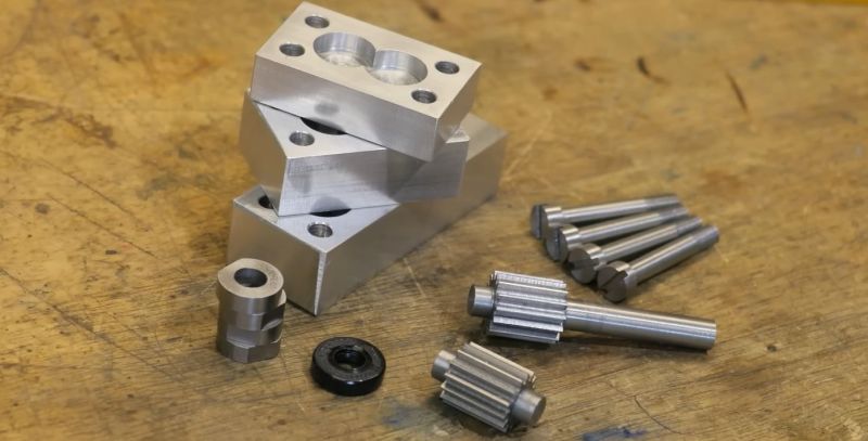
In this part one of a series on a DIY gear pump, scrap aluminium is used for the housing, along with 1045 medium carbon steel for the gears and W1A high carbon steel for bearings and other wear surfaces. Since at least one of the gears needs to be driven, a lip seal rated for 10 bar is used to provide a path for the shaft. As noted in the video, this is supposed to be a learning experience, ergo it’s a simplified design that merely targets being functional as a gear pump.
With the basic design figured out, the parts were created on the lathe and mill, followed by assembly. Most of the controversy is about the tolerances within the housing, as any leakage will reduce the efficiency. This means the spacing between the gears and housing, space between the gears and bearings, as well as that provided by the gasket that seals the housing base and top. This is where the comment section somewhat explodes with criticism and advice.
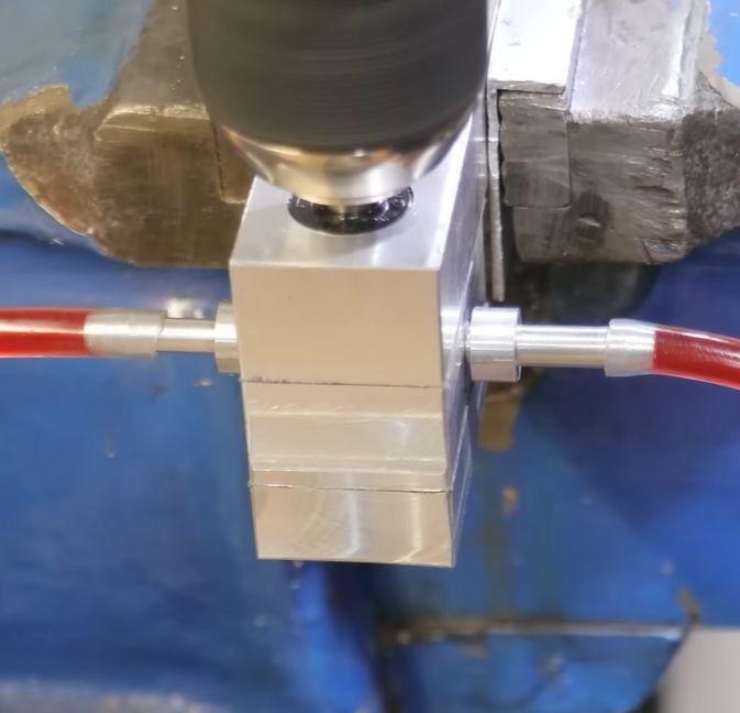
As can be seen in the demonstration with a better gasket, there is absolutely flow when driven at 1200 RPM, but also clearly severe leakage as evidenced by said flow not moving quite as fast as it should. We’re looking forward to the next part, in which addressing these tolerances is tackled, with hopefully a much more performant gear pump resulting.


I can see immediately by the poorly turned end faces of the gear wheels you will have poor performance. I went thro this 45yrs ago. For close tolerance i wld move from al. alloy end plates to a bronze.
Have you considered an Axile Piston Pump?
https://www.takako-inc.com/english/products/pump.html
micro apex seals
You asked for comments,soon, as for tolerances obviously machining with seal and gasket losses minimized. But for the gear to casing, try to oversize the case slightly and use shim stock to achieve the tolerances you will need.
Yesterday I watched blondihacks build one from scratch, but without gears. Has springs, balls and a few parts. Pretty similar to how a 2 stroke works. Seemed rather simple if you have the tools, although it’s a pistol style so you have to move it in and out instead of rotating it. She build one for her model steam train. It could push quite a bit of water.
I’m actually looking into these products as I want an inline transfer pump that doesn’t automatically fail when it runs dry, like most transfer pumps do, and can easily push up gasoline about a meter. Seems like most pumps aren’t built properly.
I don’t see anywhere in here a good understanding of the gear teeth profile themselves. It was a very long time ago and I don’t remember much of it at this point, but I had a college class on gearing. Gearing is a trigonometry class. The class teaches you how to define the shape of a gear as a matematical formula. It included a few chapters of calculations specific to moving fluids. The angle of the teeth, width to height ratio, shape of the top and bottom clearance etc, all play into fluid transfer gears. TLDR, they are not just regular gears. I don’t think using the flat type of cutter you used will produce a good fluid pump gear. You have to know the math and use a gear indexer and design the gear to me venture target amount of fluid per revolution.
I’d definitely be concerned about oil bypassing the gears by passing up and over the tops/bottoms of the gears. I’d be very surprised if the flat surfaces of the gears on the housing or against the shaft seal actually provides a good seal against backflow.
It would be pretty straightforward to measure this by testing the pressure head that the pump can generate, as well as measuring how long it takes for generated pressure to bleed down by flowing back through the pump while it’s stationary.
It’s the difficulty in achieving a level of precision required to exploit physics that makes it a great metric for measuring a nations manufacturing ability. That’s the type of precision required to exist in space.