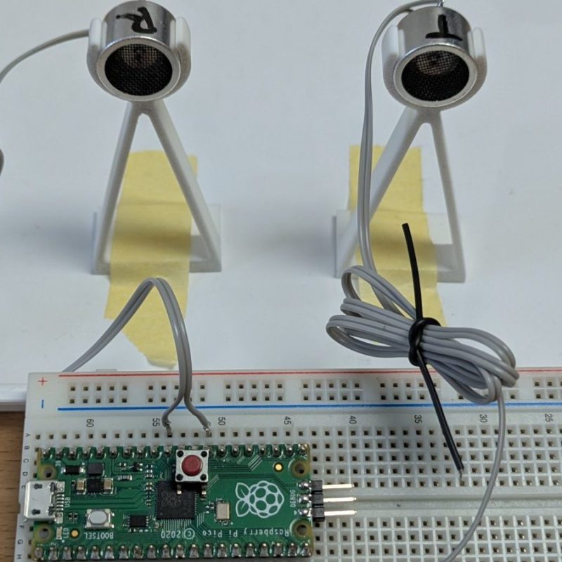
Just about every “getting started with microcontrollers” kit, Arduino or otherwise, includes an ultrasonic distance sensor module. Given the power of microcontrollers these days, it was only a matter of time before someone asked: “Could I do better without the module?” Well, [Martin Pittermann] asked, and his answer, at least with the Pi Pico, is a resounding “Yes”. A micro and a couple of transducers can offer a better view of the world.
The project isn’t really about removing the extra circuitry on the SR-HC0, since there really isn’t that much to start. [Martin] wanted to know just how far he could push ultrasound scanning technology using RADAR signal processing techniques. Instead of bat-like chirps, [Martin] is using something called Frequency-Modulated Continuous Wave, which comes from RADAR and is exactly what it sounds like. The transmitter emits a continuous carrier wave with a varying frequency modulation, and the received wave is compared to see when it must have been sent. That gives you the time of flight, and the usual math gives you a distance.
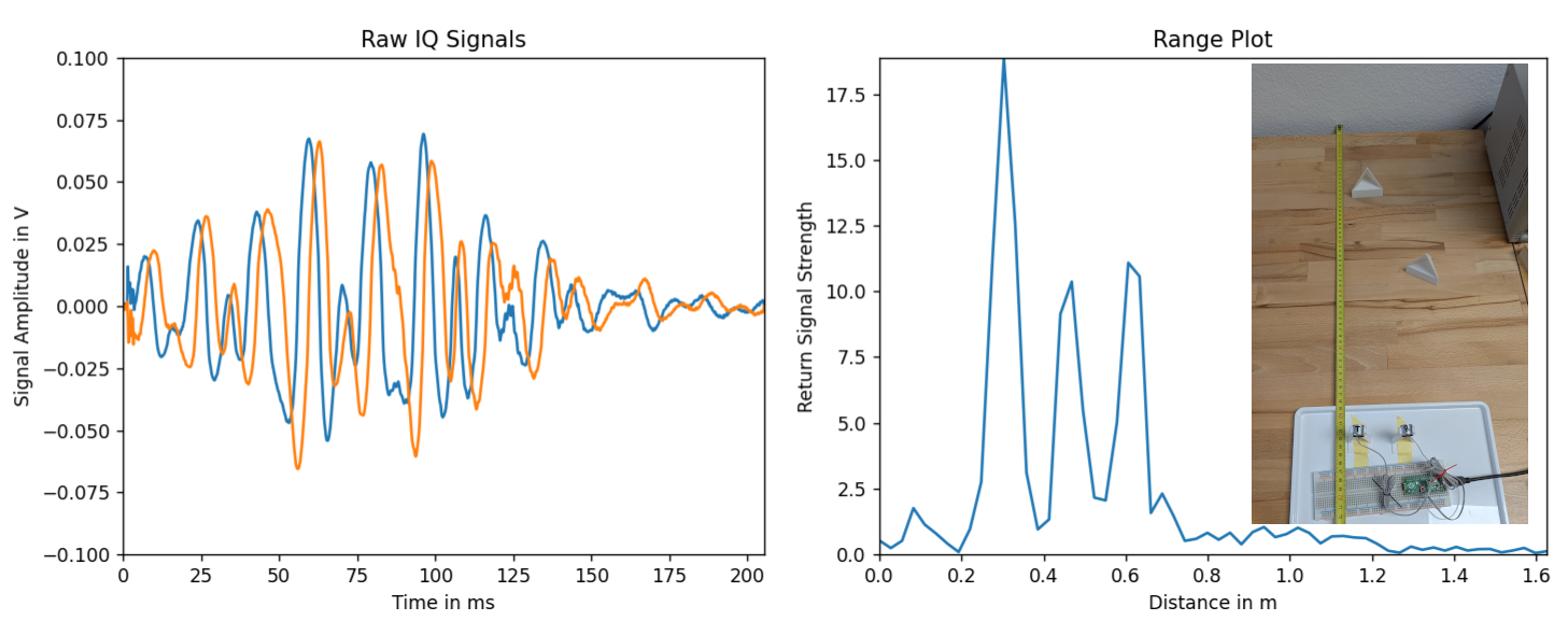
Since he’s inspired by RADAR, it’s no surprise perhaps that [Martin]’s project reminds us of SDR, and the write-up gets right into the signal-processing code. Does it work better than a chirping module? Well, aside from using fewer parts, [Martin] can generate a full range plot for all objects in the arc of the sensor’s emissions out to 4 meters using just the Pico. [Martin] points out that it wouldn’t take much amplification to get a greater range. He’s not finished yet, though — the real goal here is to measure wind speed, which means he’s going to have to go full Doppler. We look forward to it.
This isn’t the first time we’ve seen the Pico doing fun stuff at these frequencies, and Doppler RADAR is a thing hackers do, so why not ultrasound?


Piezoelectric speakers operate at “high voltage.” Some modules use a charge pump to double the voltage, while other modules use a transformer.
Analog filtering allows operation in noisy environments. With this simple circuit, it only works on a large wall and with a nearby target, turning it into a school experiment.
The difference would surely be made by several transmitters synchronized with the receiver and uploading it to an AI in search of characteristic patterns.
Due to the correlation property, the FFT peak might collect much more energy than a normal HC04 single pulse system would do. That could possibly compensate the high voltage high amplitude pulse of a normal HC04. Conclusion: The detection quality depends on the energy collected by the sensor and in the FM-CW system that energy is just distributed over time like in some ultra wide band systems.
This is very cool! I have been using an analog MEMS microphone (SPV0142LR5H-1) directly on the Pico’s ADC for quick experiments with receiving high frequencies like 200KHz. The frequency response of MEMS microphones can be much flatter than the piezos which are tuned to 40KHz, so they may allow a much wider frequency sweep to be used. Using an piezo like the MA40S4R (first reasonable result from search) for comparison the MEMS microphone looks like it has better sensitivity by more than 20dB if I’m reading the charts right.
I missed the different 0dB reference of 10 V/Pa on the piezo, so maybe it’s much closer for the peak sensitivity, but the piezo does fall off fast away from the peak.
Do you think it Is possible to do the post-process on the Pico itself, to get real-time measurements?
Maybe not in Python, but it would be great to have a standalone device giving the different positions of obstacles, using I²C to get values from another micro-controller…