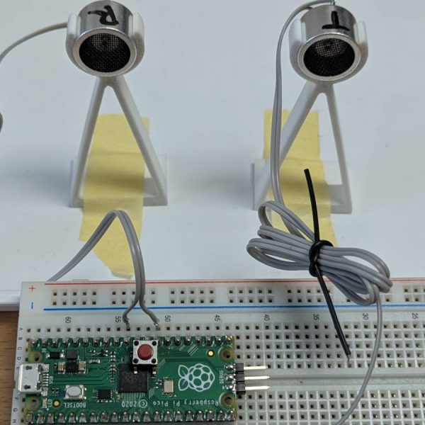
Bike-Mounted Synthetic-Aperture Radar Makes Detailed Images

Synthetic-aperture radar, in which a moving radar is used to simulate a very large antenna and obtain high-resolution images, is typically not the stuff of hobbyists. Nobody told that to [Henrik Forstén], though, and so we’ve got this bicycle-mounted synthetic-aperture radar project to marvel over as a result.

Neither the electronics nor the math involved in making SAR work is trivial, so [Henrik]’s comprehensive write-up is invaluable to understanding what’s going on. First step: build a 6-GHz frequency modulated-continuous wave (FMCW) radar, a project that [Henrik] undertook some time back that really knocked our socks off. His FMCW set is good enough to resolve human-scale objects at about 100 meters.

Moving the radar and capturing data along a path are the next steps and are pretty simple, but figuring out what to do with the data is anything but. [Henrik] goes into great detail about the SAR algorithm he used, called Omega-K, a routine that makes use of the Fast Fourier Transform which he implemented for a GPU using Tensor Flow. We usually see that for neural net applications, but the code turned out remarkably detailed 2D scans of a parking lot he rode through with the bike-mounted radar. [Henrik] added an auto-focus routine as well, and you can clearly see each parked car, light pole, and distant building within range of the radar.

We find it pretty amazing what [Henrik] was able to accomplish with relatively low-budget equipment. Synthetic-aperture radar has a lot of applications, and we’d love to see this refined and developed further.

[via r/electronics]

Homemade 6 GHz Radar, V3

The third version of [Henrik Forstén] 6 GHz frequency-modulated continuous wave (FMCW) radar is online and looks pretty awesome. A FMCW radar is a type of radar that works by transmitting a chirp which frequency changes linearly with time. Simple continuous wave (CW) radar devices without frequency modulation cannot determine target range because they lack the timing mark necessary for accurately time the transmit and receive cycle in order to convert this information to range. Having a transmission signal modulated in frequency allows for the radar to have both a very high accuracy of range and also to measure simultaneously the target range and its relative velocity.

Like the previous versions, [Henrik] designed a four-layer pcb board and used his own reflow oven to solder all the ~350 components. This process, by itself, is a huge accomplishment. The board, much bigger than the previous versions, now include digital signal processing via FPGA.

[Henrik’s] radar odyssey actually started back in 2014, where his first version of the radar was detailed and shared in his blog. A year later he managed to solve some of the issues he had, design a new board with significant improvements and published it again. As the very impressive version three is out, we wonder what version four will look like.

In the video of [Henrik] riding a bicycle in a circle in front of the radar, we can see the static light posts and trees while he, seen as a small blob, roams around:

Continue reading “Homemade 6 GHz Radar, V3”

Extremely Detailed FMCW Radar Build

A lot of hackers take the “learn by doing” approach: take something apart, figure out how it works, and re-purpose all of the parts. [Henrik], however, has taken the opposite approach. After “some” RF design courses, he decided that he had learned enough to build his own frequency-modulated continuous wave radar system. From the level of detail on this project, we’d say that he’s learned an incredible amount.

[Henrik] was looking to keep costs down and chose to run his radar in the 6 GHz neighborhood. This puts it right in a frequency spectrum (at least in his area) where radar and WiFi overlap each other. This means cheap and readily available parts (antennas etc) and a legal spectrum in which to operate them. His design also includes frequency modulation, which means that it will be able to determine an object’s distance as well as its speed.

There are many other design considerations for a radar system that don’t enter into a normal project. For example, the PCB must have precisely controlled trace widths so that the impedance will exactly match the design. In a DC or low-frequency AC system this isn’t as important as it is in a high-frequency system like this. There is a fascinating amount of information about this impressive project on [Henrik]’s project page if you’re looking to learn a little more about radio or radar.

Too daunting for you? Check out this post on how to take on your first radar project.

Guest Post: Try Radar For Your Next Project

Sensors. The low-end stuff that we can get our hands on usually suffers from poor range, lack of sensitivity, and no way to characterize what the target is. But today we can use the good stuff that, until recently, was only available to military: radar. In this post we will discuss how radar works, commercially available small radar devices, and where to learn more to help make it easy to add radar to your next project. Reach out and sense something!
Continue reading “Guest Post: Try Radar For Your Next Project”