If you’re a regular reader of Hackaday, you may have noticed a certain fondness for Meshtastic devices, and the LoRa protocol more generally. LoRa is a great, low-power radio communications standards, but sometimes the antennas you get with the modules can leave you wanting more. That’s why [Chris Prioli] at the Gloucester County Amateur Radio Club in the great state of New Jersey have got a Yagi antenna for North America’s 915 MHz LoRa band.
Right out the gate, their article links to one of ours, where [tastes_the_code] builds a Yagi antenna for the European 868 MHz LoRa. Like [tastes_the_code], the radio club found [Chris]’s antenna gives much better reception than what came with the LoRa module. Looking out their window, instead of two Metastatic nodes with a stock antenna, one club member is now connecting to two hundred.
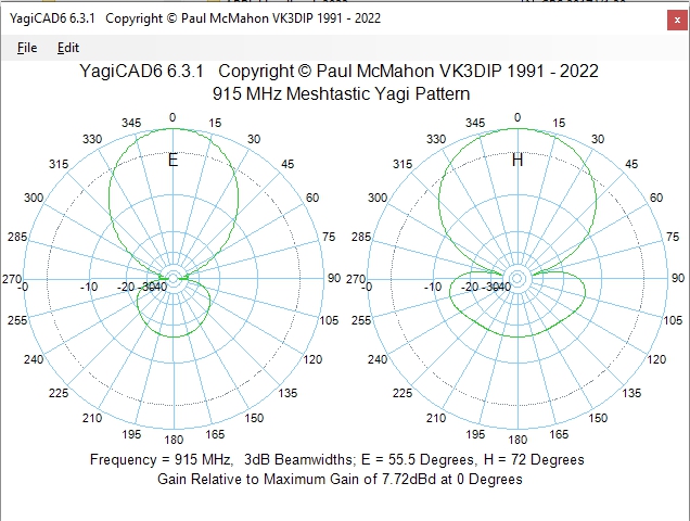
Now, the Yagi is directional, so you only get that boost pointed down the axis of the antenna, but at least in simulation they estimate a 7.7 dB front-to-back gain vs under 3 dB for an omnidirectional antenna. Not bad, for a simple 3D print and some stiff wire!
If you don’t want to re-invent the wheel again, check out the GCARC’s GitHub for files if you’re in North America. If you’re in Europe, check out [taste_the_code]’s build from last year. Of course whatever band you’re operating in, Yagi isn’t your only roll-your-own option for a LoRa antenna.
Thanks to [Jon Pearce WB2MNF] for the tip!


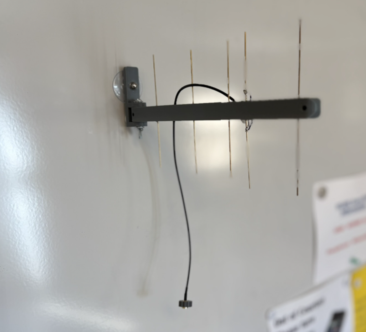
I wonder if that simulated plot includes the big steel bolt and infinite plane of dielectric right in front of the director. Maybe that’s why they got such a horrible match in the built version?
Yea, I was looking at it and thought “did they build it backwards?”
I assume it was constructed “backwards” on purpose, to be placed on the other side of the nearest wall between the antenna and the signals, but yeah the metal fasteners seem like they would cause problems.
Aiming it directly into a wall with a couple of steel bolts and a mounting bracket in front definitely doesn’t look right.
Yah that is weird……….
missed opportunity: they have could used the outermost director as a pivot for the whole antenna.
It can be fastened on the inside or outside of the window depending on your needs, always pointing out, of course. A picture of it mounted on a window didn’t work so we mounted it on the white board.
Jon, do you realize that the antenna is radiating towards the white board?
We also replaced the metal bolt with nylon in the final version.
Mind that with increasing antenna gain, you may be falling foul on the EIRP limits at the specific frequency, and to remain compliant you may have to reduce your transmitting power.
Using a better antenna to receive stuff is completely fine, but transmitting is a different matter, because a highly directional antenna will also concentrate the radio interference you cause towards anything you point it.
I think at mW strength this particular design would be ok. But, as always, don’t aim it at any body parts you deem important.
It’s not about human safety, it’s about EMI compliance. It means, because you’re operating on a license free channel (915 MHz ISM band), you should play nice with other people and respect transmitting power and duty cycle limits so other people can use it as well. The limits are in place, so the “noise pollution” you’re causing on the radio channel would drop off very quickly and not cause serious issues for your neighbors who might also want to use the same channel for other purposes at the same time.
If you’re out in the middle of nowhere, who cares, but if you’re in an urban area you might want to keep it down so you’re not interfering with someone’s garage door opener or weather station, or someone else’s LoRAWAN network etc. that operate in the same free-for-all band.
The ISM channels are specific frequencies that follow a harmonic series, that typically leads down to some military or public radar system frequency. These frequencies are free for all because they’re already full of interference and can’t be assigned to any particular use.
Microwave ovens work in the ISM frequencies because then their harmonic emissions will land on other ISM bands instead of spilling over some mobile carrier’s network and causing a whole load of lawsuits. Same with cheap consumer electronics, wifi, bluetooth, RC toy transmitters, weather stations, and LoRA modules.
With the ISM bands already filled with all sorts of buzz and noise, if everyone kept adding transmitting power or using higher gain antennas to punch through it, the situation would escalate into a shouting match. More power, more interference, more power again….
You obviously haven’t a clue as to what youre talking g about past having read a couple ‘articles’ while taking a shyte.
No military radars nor public radars use ISM. FULL STOP. NONE.
And yes, in the USA, ISM does have eirp limits. I suggest you educate yourself beyond the taking a shit stage.
To Wit:
900 MHz Band (e.g., LoRaWAN)
Max EIRP: Around +30 dBm for some devices, with stricter limits like -1.23 dBm (EIRP) for certain FSK/GFSK systems in the 902-928 MHz range.
It’s a historic point, not necessarily reflecting modern use. The point is that an imperfect radio transmitter at one frequency will will put out harmonic interference at higher frequencies, so if you’re transmitting at, say 433 MHz then you’re probably also transmitting something around 865MHz to 868MHz because you’re distorting the signal and some energy bleeds over into the higher frequency range. That’s why both frequencies are ISM, so you don’t need to be so careful about the filtering, which would be difficult for the original purpose of using these frequencies for high power radar pulses or RF heating applications etc.
To wit: you can transmit at 4 Watts from a static base station and 1 Watts from a mobile station if your antenna gain doesn’t exceed 6 dBi, without special license, as far as I can tell by the FCC rules.
If your antenna gain is 7.7 then obviously you would need to limit you transmit power to remain within the legal limits.
@tollholio
the 5ghz ISM band in the US absolutely overlaps with aircraft radar in the 5ghz area of the spectrum. Certain channels in that band are required to use DFS to avoid possible radar interference.
It only matters for analog transmissions. Digital data is DC balanced so it doesn’t pose any danger.
“Digital data is DC balanced so it doesn’t pose any danger.”
The FCC’s limits for maximum permissible RF exposure are based on operating frequency and power field density in mW/cm2.
I don’t recall any exceptions for “DC balanced” digital data.
Consider: The carrier of a 2 meter FM mobile is inherently “DC balanced.” Are you suggesting there are no power levels above which it would be unsafe to be in proximity of a whip, let alone a yagi?
There is no digital transmission, every transmission is analog.
The coding maybe is not analog.
If you’re using it with a ham radio license in the US, the power limit is PEP out of the transmitter, not EIRP. You can have as much antenna gain as you want.
Not true.
You’d have to be using it INSIDE a ham radio band.
Your ham license isnt a blanket authorization to broadcast at the 1.5kw level.
915 MHz is the 33 cm ham band in the US. The band is shared with other users including the government, licensed part 90 users, license free part 15 devices and ISM equipment.
Meshtastic has a ham radio mode that disables encryption and only allows it to connect to other ham stations.
Meshtastic is spread spectrum, so the power limit is 10W PEP, not 1.5kW.
“ in simulation they estimate a 7.7 dB front-to-back gain vs under 3 dB for an omnidirectional antenna.” Omni directional antennas do not have a front to back ratio… this is really misguided. But also the antenna is literally pointed at the wall. There’s just too much nonsense here… is it April first already?
They dont have a clue as to what the terms mean
Forward gain is one thing
Feont to back is ENTIRELY different.
As is front to side.
These morons could have created just as much gain with a better swr by using a super j pole.
“There’s just too much nonsense here”
What do you expect? We are in the “license in a day” times.
Most folks(hams) don’t even know how to build a simple dipole.
CBers, neither! They always forgot two important things!
a) to use a coaxial stub in the middle (feedpoint) to connect to coaxial cable
b) to use an 1:1 balun to connect the dipole to a coaxial cable
c) *
Both is important to avoid mismatching and a wrong radiation pattern.
A dipole (di-pole) has two symmetric sides/balanced sides, while the coaxial cable is unbalanced.
Now, if the dipole is directly wired to an, say, RG58 coaxial cable, the radiation pattern nolonger is that of a lambda 1/2 dipole.
Both sides are nolonger “equal”.
Instead, there’s one radiating antenna pole, plus ground/counterpoise.
Like with a lambda 1/4 antenna, basically. Or a broken groundplane with just one counterpoise element.
But that means that the broken “dipole” looks out desperately for ground, which is bad.
The mantle of the coxial cable then is used as makeshift ground, and RF and sheath currents (“mantle waves” in my language) are in the ham shack.
The coaxial cable then also picks up RF noise via mantle etc.
That’s really a common problem among both beginners and oldtimers.
More than often, a homebrew dipole is foolishly made the simple way without any impedance matching!
[c) in ancient times, hams had used those weird feed-lines, ladder lines, instead of proper coaxial cables. These lines were balanced, like the dipole.)
PS: a, b and c are alternative options. They’re not meant to be combined, of course. Sorry for the poor wording.
A simple coaxial stub is an alternative to using an balun.
A stub also can handle lots of RF power, while an balun essentially is a more sensitive transformer/coil.
Yet, despite that, the hobby is dying faster than Charlie Kirk.
lol no its not. Look at the number of new US ham licenses issued in the last couple of years alone.
Make sure you’re turning down your tx power to stay within legal EIRP. A yagi is very easy to blow the limit with.
The Yagi is fine, but here in good ol’ Europe the HB9CV was popular, too!
It was very beginner friendly, easy to build and the default antenna for fox-hunting (aka foxoring, directional finding) on 80m and 2m amateur bands.
Wow – I didn’t anticipate this much confusion about the picture, but a critical point was omitted from the Hackaday description. To clarify – you do NOT mount this antenna on a metal white board pointing towards the board inside of a room. Instead you mount it on a WINDOW, either inside or outside (the boom is drilled to allow mounting at either end) pointing OUTWARDS. The picture is that way because attempting to photograph something mounted on a window results in the camera focusing on objects outside of the window, and it’s hard to get the intended subject in focus. The paragraph above the picture on our website begins: “To mount the antenna securely on a window while pointing outward…” so I thought that the intended use was obvious and therefore didn’t take more time in trying to get an accurate picture. Apologies to anyone who believed that the antenna was intended to be used as depicted.
Re the gain figures, note that our website does not refer simply to an “omnidirectional antenna” but rather to “typical stock omnidirectional antennas”, which for these radios are often shortened half-wave dipoles that have gain in the 2-3 db range. I didn’t write the Hackaday text that shortened that sentence.
We did the ERP calculations based on the output power of the typical 915 radio using this antenna and found it to be well within the legal ERP ranges.
Our goal here was to (a) show and provide building details of an antenna that our members have found to significantly improve the effectiveness of their 915 radios and (b) to create a potentially interesting group project, which involved about two dozen of our members in a work session for a couple of hours. If your goals coincide with either of these, you’ll hopefully find this project useful.
Thanks for the clarifications Jon.
Say, do you want to write for HaD? ;-)
What calculations, id be interested to know.
900 MHz Band (e.g., LoRaWAN)
Max EIRP: Around +30 dBm for some devices, with stricter limits like -1.23 dBm (EIRP) for certain FSK/GFSK systems in the 902-928 MHz range.