
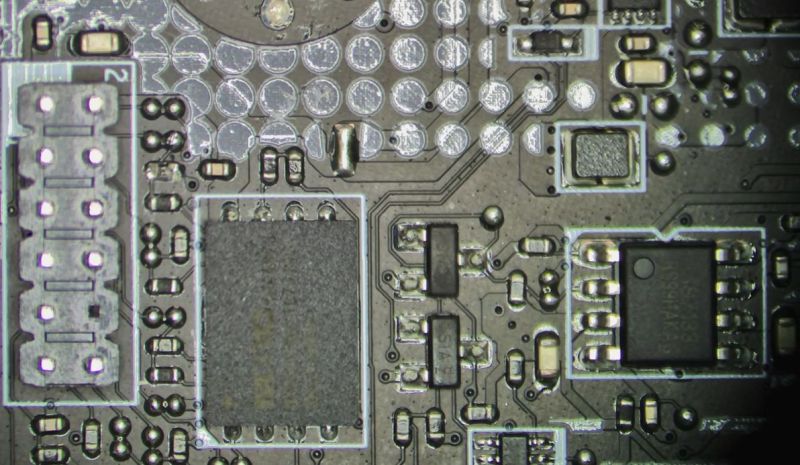
Doing board level diagnosis on a PCB is hardly black magic, but some PCBs are definitely more daunting than others. The Socket LGA 1851 mainboard that [Fix the Pixel] got in for repair being one of the harder cases due to the sheer size and complexity. Adding to the excitement was having to purchase a used CPU for it off eBay to even test the board and work through the boot-up sequence to find the culprit.
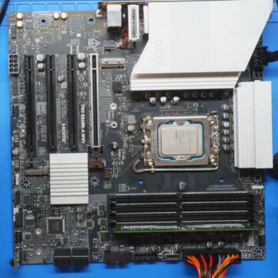
A basic understanding of how these mainboards power up and verify that they can move on to the next phase is essential here, starting with the power rails. Although the culprit turned out to be a single missing 5.1 Ohm resistor on an SPI clock line, you still have to reason your way through the diagnosis. For this mainboard the boardview was fortunately available, but that still doesn’t make it easy to spot components that have quietly left the chat.
With the CPU and RAM installed the board doesn’t bother to boot up, with the VRM controller for the CPU’s power phases showing its enable pin to stay low. Going down the list of conditions for this pin to be pulled high the culprit was eventually found, when the PCH – the board’s chipset – never reading the BIOS chip.
Checking the SPI lines on the mainboard near the BIOS chip quickly showed the knocked-off resistor on the SPI clock line. Soldering a fresh resistor in place resulted in the board happily booting up once more. Although having a boardview here available helps a lot, checking such basics like the SPI line resistors around the BIOS can be a quick checklist item before dragging out the big diagnostics guns or shelling out money for a boardview file.








Please be kind and respectful to help make the comments section excellent. (Comment Policy)