Introducing The Periodic Table Of US Electrical Receptacles

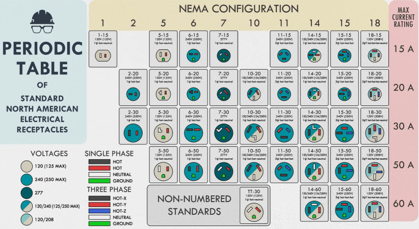
Although things may seem simple on the North American grid as an end-user if you limit yourself to just 120 VAC and NEMA 1-15 and 5-15 connectors, there is a veritable zoo of different voltages and receptacles out there in the NEMA connector catalogue. Recently [Practical Engineering] decided to not only take a look at how many of these defined standards are actually used, but also put them in a nice periodic table style graphic.

Responsible for these standards is the National Electrical Manufacturers Association (NEMA), which as the name says is a collection of manufacturers. Founded in 1926, this US trade association also affects outlet standards in countries like Canada, Mexico, Japan and so on. The caveat here is that compatibility between e.g. a similar looking Japanese 1-15-style plug and a US 1-15 outlet is not guaranteed, even if you ignore voltage and grid frequency differences.

In an ideal world everyone would agree on a set of reasonable connector designs and we could move on, but we live in a world where even today designing your own national connector instead of picking something like the ubiquitous Type F is considered to be reasonable. At least it’s not susceptible to the ‘penny challenge‘ flaw that the NEMA 5-15 connector suffers from, but that’s small comfort.

NEMA connectors are also unique in that they are often polarized, while Type E/F and others rarely are, putting the onus of dealing with AC polarity on the device. This already shows why the NEMA connector diversity exists, as this trade association wanted to have specific connectors for different polarities, different current limits and also the nearly half a dozen of different voltages commonly used throughout the US.

This ‘one connector for a specific combination’ approach means that quite a few of them are not really used in real life, though from a European perspective where you deal with Type C (‘euro plug’) and Type E/F (‘Schuko’)  on ~240 VAC and triple-phase 440 VAC connectors if you run a heavy machine shop or want to fast-charge an EV at home, it’s still a bewildering number of active combinations.

Continue reading “Introducing The Periodic Table Of US Electrical Receptacles” →
Dissecting A Lethal Universal Travel Adapter

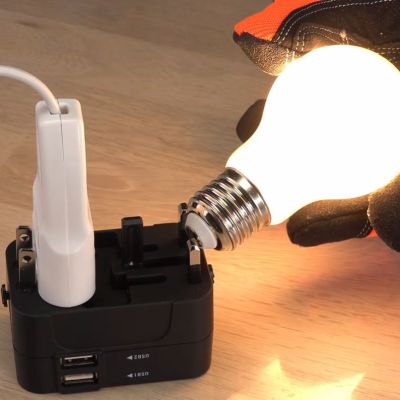
The world’s refusal to standardize on a single type of mains power outlet has led to a vibrant market of so-called travel adapters, all of which try to outdo each other in convenience and universality. This comes at the cost of complexity, something which ultimately reflects in the price. The cheapo $9.26 universal travel adapter that [Brainiac 75] got off an online retailer’s site is thereby a good example of how safety suffers if the overarching goal is to ‘make it cheap’.

The first exciting discovery is that when you plug any of its three sets of connectors into an outlet, the others become live at the same voltage. This would suggest that they’re just wired together, a fact soon confirmed with a quick resistance check between the respective prongs. Though to the adapter’s credit, the prongs are not live when fully retracted into the enclosure. Yet as demonstrated in the video, the retracting of prongs is not enforced, so mistakes here are possible.

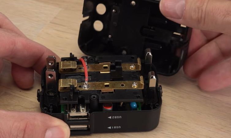
The adapter also has two USB ports that claim to provide 5 V at 2.1 A, with as it turns out no hard cut-off. This is probably the best part of the adapter despite not featuring any advanced charging features. After opening the adapter, you can see that the sliding mains prongs connect to a central bus bar when either unfolded or extended, which is definitely straightforward, but doesn’t enforce that only one type of prongs can be used at any given time.

To make it safer, [Brainiac75] removed the less useful US and UK plugs, taping over the empty holes. It’s now just a USB charger with a universal mains port to plug random non-EU plugs into, which is probably relatively safe and a better idea than really using it as a travel adapter.

Continue reading “Dissecting A Lethal Universal Travel Adapter” →

Decoding RF Link Using A PC Soundcard

[Ray] wanted to use a microcontroller to send signals to some wireless power outlets. Instead of tapping into the buttons on the remote control he is using an RF board to mimic the signals. There are two hurdles to overcome with this method. The first is to make sure your RF module operates on the proper frequency. The second is to get your hands on the codes that are being sent from the remote control unit.

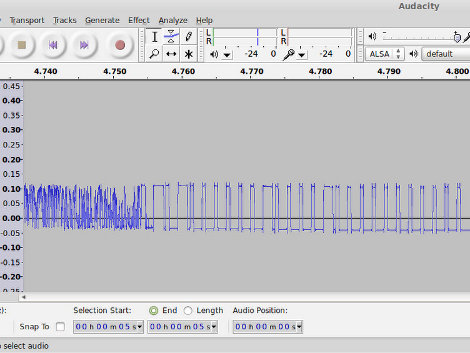
Now you could just hook your oscilloscope up to the transmitter and take a look at the timing of the signals. But most hobbyists don’t have that kind of high-end test equipment in their basement or garage shops. [Ray’s] approach uses something we all have available to us: a sound card and some open source software. He connected the data pin from his RF receiver to an audio plug and inserted it in the line-in jack of his computer. Using Audacity he recorded the signal as he pressed buttons on the transmitter.  This method not only captures the data, but the time stamps native to the audio editing program let him easily work out the timing for each signal.

It’s kind of amazing what you can do with this audio analyation technique. Earlier this year we saw it used to measure response time for DSLR cameras.

Continue reading “Decoding RF Link Using A PC Soundcard” →