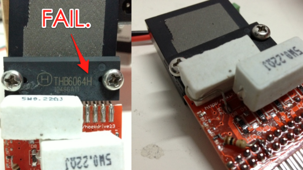
This one is a bit dated, but the lessons are still relevant. [Zach Hoeken] posted about the challenges he faced building a CNC stepper driver. He was experimenting with Toshiba motor drivers back in 2012.
The modular motor driver boards he built were based on the THB6064AH – capable of 1/64th step, and 4.5 Amps at up to 50V. [Zach] built a test jig to run the boards through their paces. A couple of messed tracks was the least of his problems – easily fixed by cutting traces and using jumper wires to correct the errors. But the header footprints for the motor drive boards got reversed. The only way out was to solder the headers on the back side.
LESSON : Always check footprint orientation and pin numbering before sending boards to fab.
The surprising part was when someone as experienced as [Zach] messed up on Ohms Law. Based on the current he wanted the motors to run at, his sense resistors needed to be 3.2W, but he’d used SMD footprints (0805 likely) instead. Those tiny resistors couldn’t be used at all, and the 5W resistors plonked on looked like an ugly hack.


