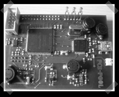
[lekernel] sent in his USB logic analyzer. I might just have to build this one for my work bench. It’s based on an Altera Cyclone 2 FPGA and he’s provided full schematics, source and a quick and dirty Linux driver to get things going. The board is nearly all surface mount, but he points out that the entire thing was soldered with a standard iron and de-soldering wick. If you’re looking for a good starter FPGA project, this looks like a good one.
I started writing for Hack-A-Day a little over a year ago. I’ve barely taken a break, but for the next week I’m going to be taking some serious time off on a Caribbean island. Thanks for a great year guys! While I’m gone, [fbz] has kindly consented to take over the reins. I’m looking forward to another year when I get back, but right now I’ve got to finish packing my dive gear.


sounds like you’re going to Grand Cayman. I’m living there right now for Medical School (i’m from S. Fl). Great diving here.
Soldering this could’ve been done ever simpler. I’ve soldered 10+ FPGAs using nothing but soldering iron and some SMD flux. No wick, no overheating – entire soldering in 3 minutes (1 minute preparation, 1 minute soldering, 1 minute checking). I might post some videos someone wishes.
Also, I see no need for a kernel driver – it’s much faster, easier and safer to write a userspace driver using libusb. Plus, it’s portable – both between kernel/distro versions (without recompiling) and to Windows (!).
You can also do it without a soldering iron by using (leaded) solder paste and a frying pan. You get perfect joints everytime, and the soldering paste make components ‘self center’ during reflow. it’s magic.
For a few components, you can also use solder paste and one of these cheap ‘gas’ soldering irons : they usualy come with a hot air tip that works wonder for smaller components with paste.
This project is interesting, I’m already looking into that switching regulator he uses…
happy birthday hackaday!
and impressive soldering.
Wow… if the previous people could maybe link to some guides on how to do those techniques I would be interested.
As it is I am very impressed by this guys soldering skills.
Regarding soldering multi-pin SMD devices; the solder wick approach is a little nasty in that it’s difficult to lift the right ammount of solder off, but it can be done.
The better approaching is not to put too much solder down in the first place.
I regularly hand solder these type of devices:
1) Locate the part on clean pads with tweezers.
2) Lightly solder a corner pin or two, check location is good.
3) Apply plenty of liquid flux.
4) Create a small ball of solder on a few pins at one end of the row.
5) Heat ball of solder, whilst wiggling the iron and slowly move along the row. The surface tension on the solder ball will pull it along to the next pins, leaving previous pins soldered.
6) Apply more flux/solder where needed.
7) When you get to the end of the row, the ball should be all used up if you got it right. Otherwise clean off excess solder with wick.
8) Repeat for other rows.
9) Clear off flux with flux-off.
Couldn’t be simpler ;-) I’ve seen our very skilled tech use a hot air gun for BGAs but that’s beyond my skills.
Simon
I happened to find something similar to this today:
http://www.sump.org/projects/analyzer/
“FPGA Based Logic Analyzer”
“The project includes the actual analyzer in VHDL (for Spartan 3 FPGA) and a PC Software for the end user. The design employs a FPGA board that can be obtained easily.”
” * 16 channels at 200MHz sampling rate
* 32 channels up to 100MHz sampling rate
* state analysis up to 50MHz using external clock
* 256KSamples memory”
kosma makes a good point about using user space interfaces rather than writing kernel code. Although writing drivers on non NT systems is actually fun at times.
That’s also some impressive etching(?) and soldering. The traces actually look micro cut.
tj, pcbpool makes ‘real’ pcbs, they do not make them the amateur way. There are various websites that propose ‘prototype’ boards, some of them are very reasonable in price.. And getting a ‘pro’ board is quite necessary, for this kind of track density…
There is an ongoing discussion at [url=http://www.avrfreaks.net/index.php?name=PNphpBB2&file=viewtopic&t=51595%5DAVRFreaks%5B/url] with various links and user experience, if you are interested.
@Kosma: I have tried the solder flux method on an old PC motherboard. It made lot of short circuits that were really tricky to remove without wick, so I gave up this one. But probably my soldering iron was not powerful enough to heat the multi-layer PCB or my flux was a bit old.
Also, I have also tried libusb, but I wanted to play with advanced USB options (isochronous endpoints, …) so I wrote a kernel driver. But you’re right, libusb would be more appropriate with the current protocol.
@BusError: I bought the switching regulators from Radiospares (also available from Farnell). They’re a bit expensive, but they work great and are easy to use.
Also soldering boards using a frying pan is really not a good idea. You have no control over the temperature (which can go far above that of a soldering iron, if you’re using a gas stove), and it won’t be uniform so some areas will overheat (with probable damage to the board) and in others, the solder paste will not melt.
However, this method is probably acceptable if you want to scavenge a high pin count SMD part from a board you don’t care damaging.
@lekermel:
Hmm I use a rather ‘expensive’ frying pan that has a very thick bottom that is marketed to ‘diffuse’ heat properly. I measure the temperature using an infrared thermometer and the heat is quite homogeneous for this kind of surface.
The heat is also very easy to control manualy with the knob; I set it to about ‘half’ to get the start of the heating curve right, and after about 2 minutes I push it to 3/4 to reach the reflow temperature before stopping it completely once all joints are done.
It’s fairly easy to monitor the temperature with the infrared device (target the black pan bottom, not the board).
I haven’t tried really large components yet (biggest so far was 64 pins) but a mixture of connectors (.5mm pitch) and other medium to small SMT and they all reflow beautifully.
I really want to get into FPGAs seriously and make my own boards with them, I guess I’ll soon have to give it a try :-)
This is goo stuff.
-Victor
=================
Check out fun stuff about FPGA at http://www.fpgaCentral.com
The link (http://lekernel.lya.eu/ula.html) appears to be broken; anyone have a mirror?
Thanks!