This week’s How-To comes from our newest contributor: Logan Williams.
This simple guide will show you how to build a digital synthesizer that generates and manipulates square waves. Your synthesizer will have one oscillator, which produces a variable pitch controlled by a potentiometer, as well as an LFO which modulates that pitch at a variable frequency. The part count for this project is quite low, and it can be built for under $20.
Finding the Parts
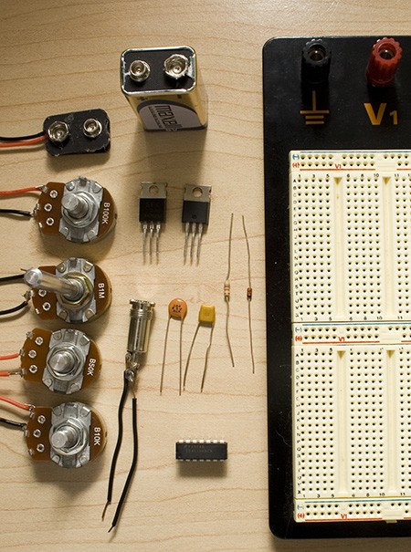
The first step in building this digital synthesizer is to procure the parts that you will need. Most of these can be bought at RadioShack, but RadioShack’s prices are often much more expensive than ordering online. All of the parts for this project can be purchased at Jameco, Digi-Key, or Mouser. We’ve provided Jameco part numbers below. If you don’t mind waiting, this is the best way to order parts.
| Item | Name | RadioShack | Jameco | ||
|---|---|---|---|---|---|
| 9V Battery Clip | 270-325 | $1.99 | 11280 | $0.30 | |
| 100K Linear Potentiometer | R2 | 271-092 | $2.99 | 255696 | $1.35 |
| 1M Linear Potentiometer | R3 | 271-211 | $2.99 | 255582 | $1.35 |
| 50K Linear Potentiometer | R4 | 271-1716 | $2.99 | 255549 | $1.35 |
| 10K Linear Potentiometer | R5 | 271-1715 | $2.99 | 255522 | $1.35 |
| 9V Battery | |||||
| IRF 510 MOSFET Transistor | Q1 | 276-2072 | $1.99 | 209234 | $0.69 |
| 3.5mm Audio Connector | 274-333 | $2.99 | 109496 | $0.53 | |
| 7805 5V Voltage Regulator | IC1 | 276-1770 | $1.59 | 51262 | $0.20 |
| 0.1 uF capacitor | C1 | 272-135 | $1.49 | 151118 | $0.20 |
| 1.0 uF capacitor | C2 | 272-1055 | $1.59 | 544956 | $0.20 |
| 40106 Hex Inverter | IC2 | Fairchild | $0.00 | 785071 | $0.47 |
| 47K Resistor | R1 | 271-1342 | $0.99 | 690540 | $1.00 |
| 1N4148 Diode | D1 | 276-1620 | $2.59 | 1537969 | $0.27 |
| Solderless breadboard | 276-002 | $14.99 | 20723 | $9.85 | |
Not Pictured
| Item | Name | RadioShack | Jameco | ||
|---|---|---|---|---|---|
| 22AWG Solid-core | 278-1221 | $5.99 | 36792 | $6.59 | |
| Amplified speakers | |||||
Tools
| Wire strippers |
Note: The potentiometers and audio jack must be either taped or soldered to 22 AWG solid core wire. Soldering is highly recommended, as it produces a more secure connection.
Creating an oscillator
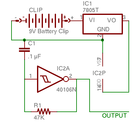
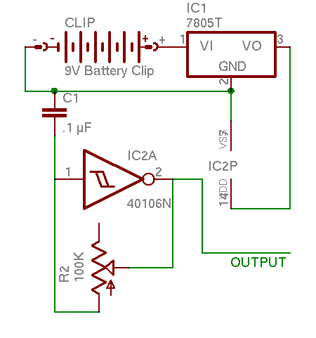
Before we can begin with the digital synthesizer, we must generate the correct voltage. Most of you will be familiar with using a 7805 5V voltage regulator. It is very simple; connect the +9V from the battery to the left hand pin, ground the middle pin, and the right hand is +5V.
The most basic circuit in any synthesizer is the oscillator. A square wave oscillator constantly alternates between two voltages, in this case +5V and 0V. We have a logic inverter to create this, which operates quite simply; if it is given +5V in (a logic 1), it give
s 0V out
(a logic 0) and if it is given a logic 0, it gives a logic 1 as output. When the input and output are connected together, it will oscillate rapidly between those two values: a 0 goes in, comes out as a 1, goes in, comes out as a 0, and so on.
The problem is that it oscillates much too fast. A resistor capacitor (RC) delay circuit can be added to slow it down. This forces the output current to charge the capacitor before it can pass through to the input. The resulting brief delay slows the oscillations to audible frequencies.
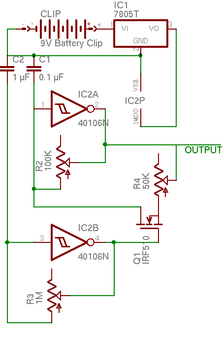
To build the oscillator, assemble the schematic below on a breadboard.
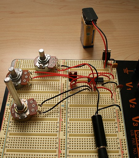
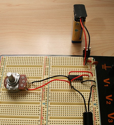
When done, the oscillator should look something like this:
Connect one side of the audio jack to 0V and the other side to the output, and it will sound like this:
Controlling the oscillator
We can make things more interesting by allowing the user to change the frequency. We replace the constant resistor R1 with a potentiometer, such as the 100K R2. This is a simple change to do, and is reflected in this altered schematic.
Now the oscillator sounds like this:
Much more interesting. Try playing an actual song, if you dare.
Duty cycle adjustment
We can add some basic timbre control to make the oscillator more interesting. The duty cycle of a square wave is how long it spends at logic 1 vs. at logic 0. For example, a wave that spends 1 ms at +5V and 1ms at 0V per cycle would have a 50% duty cycle. 1.5 ms at +5V and 0.5 ms at 0V would be a 75% duty cycle. To adjust the wave’s duty cycle, we can add another potentiometer and diode to the circuit. When the input is high and the output is low, current will be able to flow through both potentiometers, decreasing the amount of time it takes to charge the capacitor, and increasing the duty cycle.
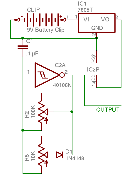
It should sound like this when completed:
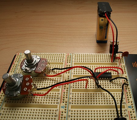
Creating an LFO
A low-frequency oscillator (LFO) is an oscillator that oscillates very slowly, from 1 to 100 cycles per second. We will use an LFO to alternate the pitch of our oscillator between two different frequencies. This can be used for siren like sound effects, timbre control, or musical sequences.
The circuit to control the LFO is slightly more complex than the ones we have used before. Because it uses a capacitor with 10x the capacitance, and a potentiometer with 10x the resistance, the oscillations are 100x slower than our first oscillator. The LFO connects to the gate of the IRF 510 MOSFET transistor. When the output of the LFO is +5V, the transistor connects its source and drain pins. With these pins connected, current can flow through the second potentiometer, increasing the pitch. When the LFO returns to 0V, the potentiometer is disconnected, and the pitch drops back to its original level.
There are quite a number of sounds that can be produced with the LFO, such as this:
and this:
Conclusion
You have now made your own simple digital synthesizer. Keep experimenting with different control methods. The frequency is adjusted with just resistance, so almost anything can be used for an input. Try a photocell, or a flex sensor. Try combining the LFO and the duty cycle adjustment. Try using it to actually make music! We’d love to see what you come up with.


Never mind, it worked!
I just had to invert the output once again as somebody already said here.
@karlbe:
If its working, and your system is running at 5VDC, you should be able to set your DMM to read AC voltage, and you should see some voltage (you’ll probably see 3.5VAC unless you have a nice meter).
If its NOT working, but the 40106 inverter is working correctly, you should see 5VDC difference between pin 1 and 2.
Best thing to do is take a DC and AC measurement from every pin on the 40106 to ground (the – terminal of the 9V). Report back here!
Is there a guide for beginners to this project? I’m a beginner, and I really want to build my own synthesizer. I bought all of my parts from a generic electronics supply shop, and I noted some differences from my parts to the parts shown on the breadboard circuit. Now I haven’t learned about the functional difference between a disc capacitor and a ceramic capacitor, but I’d imagine that they are the same.
If I am mistaken, please say so before I continue with this project. I intend to wire everything together as is (both on the circuit and as a circuit altogether), but this guide is pretty much designed for bread/printed circuit board users.
Now you may or may not think that I’m crazy, but wired circuits are less prone to destruction when crushed and (when insultated) water damage than printed circuit and breadboards. Not only that, but I can make the circuit more compact, which is what I am aiming for.
tl;dr I’m a beginner, I really want to build this project, but I need extra help. If help can be provided, that would be great.
On a side note, what’s a good electronics site for people like me, who want to be able to understand a circuit like this (and other) circuits like professionals/hobbyists?
Bear in mind, nothing about this is actually digital. It’s a completely analog synthesizer circuit.
Hey thanks for the tutorial, I always wanted to build some circuit and now I did. yay
is it possible to get polyphony out of the single 40106? i can’t get it to happen.
I just dont get I do think i understand breadboards or something because this is the umpteenth tutorial I tried to follow and the umpteenth failure I have.
http://www.flickr.com/photos/pandabrand/2529688175/
is a picture of what I am currently doing wrong. I put this together and I have no sound. If anybody’s feels kind enough to show a idiot what he’s doing wrong it would be greatly appreciated.
@pandabrand:
Hi. I just built this circuit. I’m just getting started in electronics and I don’t know nearly as much as anyone else here, but I’ll try and help you. The first thing I notice is that it looks like you have resistor r1 and capacitor c1 connected to a row which has nothing in it.
As someone else mentioned, you will need to double invert the output to get sound. This just means that you will need to connect pin 2 to pin 3 and then pin 4 will become your output. A diagram of the ic might help explain this better:
http://www.alldatasheet.com/datasheet-pdf/pdf/50835/FAIRCHILD/CD40106BCN.html
The output will need to be amplified for a speaker as the 5v the ic provides is not enough. To do this, I just took a npn transistor, connected pin 4 to the base, 9v to the collector, and one wire of the speaker to the emitter. That may not be the best way to do it, but it worked for me. The other wire of the speaker goes to ground.
As for breadboards, here’s a picture to help explain how they are connected:
http://ece-www.colorado.edu/~mathys/ecen2250/lab01/breadboard90.png
One thing that really helped me was going off of the schematic instead of the pictures. There are many sites that will teach the basics of reading circuit schematics, it is easy once you practice a bit. I hope I was able to help a bit with my very limited knowledge.
C1 should be connected to gnd and then to pin one of the hex inverter ic. Resistor r1 should be connected from pin 1 to pin 2.
@60
Thanks so much. I totally was having a mental block about this and just couldn’t get it together; your links and esp. the last comment were things that help me get over it. I now have aworking piece!!! thanks again.
This is one of the best hackaday articles… EVER
I’m going to put it is a tiny box and use it for live performances…
In answer to comment 12 by flump
You can buy all these parts from Maplin electronics. Most major towns and cities in the UK have a Maplin shop
Hi, I just found this post by accident while looking for some 40106 info.
It looks and sounds really cool, and I’ll definatly be trying this myself!
thanks
This works!!!!! THANK YOU SO MUCH. this was my first electronics project and it works beautifully. Great Job on the Tutorial. THANK YOU THANK YOU THANK YOU!
Thanks again feller, works great!
I’ve combined the finished piece with a ‘bent ‘alien voice changer’ toy, which amplifies it very nicely…
Quick note though – the final schematic doesn’t correspond with the final photo. According to the photo pins 1 & 2 are connected to 1meg pot (not 100k which the schematic states). I think there may have been a couple more minor differences, but I just experimented on the breadboard until I got it to sound good.
PEACE.
Can someone suggest an “amplified speaker” because I don’t know enough to know what I want to buy. I see that hooking these circuits up to a the first speaker I found in a box of junk only produces a crackling when the clips are (dis)connecting but when I use an old ear-piece I can hear what I believe is the expected set of tones. I wandered around a Radio Shack but didn’t find anything that seemed likely.
amplified speaker is one that has an amplifier built in (a volume knob etc) – i shouldnt think a simple speaker wont have enuff power to be audible from this circuit (or be v. quiet) – hope that helps :)
THANK YOU very much for including convenient direct links to the parts…as well as all the rest of the info, very much appreciated!
I ordered everything that you suggested, followed your directions and got it to work. It’s really fun to work with! Thanks for this resource! I would definitely use others like it in the future.
I intend on using this and other resources I have gathered in a noise act that I am to do for my friends band.
This is great. To be honest, this is my first project, but my synth turned out fine. I also added a few push to break switches to chop the sound up a bit.
Thank you very much for the tutorial.
If anyone could point me the direction of a sine, sawtooth or triangle circuit, I’d really appreciate it.
can anybody identify the manufacturer of the breadboard for this project? i know there are hundreds of them out there but we are looking for this one…..
hello im from argentine . i want to know a replacement for the mosfet transistor???????
thanks and sorry for my english
I’m new to reading schematics…
At “IC2P” on the wire between connection 3 and the ground of the 7805T voltage regulator, the connections are labeled “14DD” (with a slash through the “4”) and “VSS” (with a slash through the 2nd S). I realize that 1,4,VDD, and VSS are all connections on the hex inverter, but I can’t figure out what the slashes are for or if “DD” is referring to “VDD.”
Hope that wasn’t too difficult to follow… Any explanation?
awesome.
Could I use a 7404 hex inverter instead of 40106?
When ordering from Jameco,
part number 690540 appears to be a 47 ohm resistor, not 47kohm resistor.
The correct part seems to be 691260.
If I’m correct, you may want to update the parts list
is there any way i could run this to a computer,
for example usb safely?
i totally made one of these today….
i didn’t have a breadboard, so i just went ahead and proceeded to dive right in(not recommended). but alas, IT WORKS!! i’m happy.. thank you for sharing you schematics
This is INFACT DIGITAL! it is NOT analog.. analog circuitry use Op Amps, not Inverters.. Hex Inverters are digital…. hope this clears things up
Is there an alternate schmitt trigger instead of the 40106 hex inverter??
if one were to install in input jack (for the purpose of daisy chaining multiple LFO synths), where would that go on the circuit?
hi, i’m returning to confirm that the 47 resistor jameco link still hasn’t been changed to 47K resistor. (THANKS ilovegreenmonster) again, the current Jameco part# is 691260. the reason i’m doing this is that i thought i had a 47K when i actually had a 47. this caused me much confusion when i tried to use the leftover hack-a-day parts for a “weird sound generator” build. I highly recommend the “music from outer space” website for new synth builders. any suggestions for other sites with detailed walkthroughs of diy stompbox/synth builds, etc would be appreciated!
here is a resistor code calculator to make sure you have the proper parts: http://www.hobby-hour.com/electronics/resistorcalculator.php
err… having major problems with this… in th final image, is the picture or the chematic correct?
also, i have, i think got everything wired up, but only the 1M potentiometer does anything, and its all very quiet…
can someone post a picture of the finished article, so that i can see what im doing wrong?
thanks
Please help me!
I’m doing this for my science fair project, and it won’t work properly.
I don’t know what’s wrong with it.
Could someone make a video on this?
Cheers,
Mike
@nick
Do you think you could send me a video of the first assembled schematic?
Seeing as you’re the most active visitor on this article currently.
it’s michaelman311@hotmail.com
I just built this schematic as a first year ee student, havn’t taken a circuits class yet. It’s one thing to just build this but I really wanted to understand what was going on, so I talked to a professor who helped me out. Hope this helps anyone out. I’ll be referring to the last schematic with an LFO.
Basically what happens is that the 9V gets converted to 5V through the voltage regulator.
Then the 5V charges up the capacitor (plotted on a Voltage/time looks something like this except it only goes up to 5V http://www.kpsec.freeuk.com/images/charge.gif)
The HEX inverter has a THRESHOLD value that is somewhere inbetween 0 and 5V and when the capacitor (.1uf) has charged right above the threshold value, the output wave goes up and then comes back down when the capacitor starts to discharge and crosses the threshold value again.
The 100K potentiometer changes the audible frequency.
As for the LFO it is produced using a MOSFET transistor. The one in this case is an N type doped. It has a source, a drain and a gate (the middle pin). The transistor works as a switch that is triggered on an off by a voltage. An N type transistor opens when it is supplied by a positive voltage.
That is where the 1M pot, 1uf capacitor and HEX inverter come into play. They provide another output square voltage wave that triggers the MOSFET transistor to turn on and off. The tuning of the 1M pot gives a faster/slower square wave that determines how fast the MOSFET is triggered on/off and how quickly the two tones are heard. When the MOSFET transistor is turned off, the 50K potentiometer is not apart affecting anything. when the MOSFET is on the source and drain are connected and the 50k potentiometer is in effect. The pitch then alternates between two tones.
Hope this clears up and feel free to comment if I got anything wrong.
i can`t find the soundfiles in the flash players.
wanted to hear this melody once again :-)
is there another link?
Like the Nintendo Wii, there’s a piss-poor library for the DS
Can someone help me, i’ve wired up everything according to scamatics, but i’m not getting anything. I couldn’t find the right jack so i’m using a quarter inch phone jack, does that screw it up? I can only get sound if i pull the headphone slightly out.
Hi! I think that most simple way to make Analogue LFO Frequency Modulation is to attach MOSFET (or some similar amplifier) to capacitor which is driving the CMOS inverter (oscillator). The almost-sine-wave/almost-triangle signal is already there:
http://brmlab.cz/_detail/project/cmos_oscillator_capacitor_voltage.png
http://brmlab.cz/project/circuit_bending#simplest_possible_cmosmosfet_lfo
Note that MOSFET can be connected in parallel with the resistor/pot determining frequency of another oscillator.
Hey, nice one. I’m goin to try it! Unfortunately,I can’t play the audioexamples, could you repost it somewhere, if they still exist?
I built this thing and it’s pretty awesome. The issue I’m having is I want to mount everything in a portable case with its own speaker, but I don’t know exactly what I need to do so that it doesn’t need to go into powered speakers. This isn’t going to be a large speaker by any means, it just needs to be loud enough to have fun with it. I got it working using a very small piezo driver, but it’s really quiet. Right now the output is putting out .266 volts and I figure that’s probably not enough. Anyone got any suggestions?
@Bonham79 not sure if you’ve already gotten your answer, but it sounds like your issue could be using a stereo male with a mono female, or vice versa.
yeah… it’s actually analog using a logic gate. the signal may be digital (on/off: square wave) but the pitch control is analog. if this were a truly digital synthesizer, the pitch control would be quantized giving you a finite amount of pitches.
I built this and they work great. I used the schem and the pics, they have slightly different values. Both are cool. My problem is I’ve stacked four on top of each other and now they seem to modulate each other with or without the LFO or duty cycle engaged. Anybody know what’s going on?
I figured out my problem was due to some bad grounding while busing two breadboards together. Not sure what was happening but rebuilt on one board and it sounds as expected. Loud too! I’ve added switches to engage LFO or duty cycle as well as individual and overall volumes controls.
There are easier ways… All you need is a mic, a computer capable of running UTAU smoothly, and someone or something to provide the voice…
Nice tutorial, but it should be renamed. There is nothing digital about this circuit. It’s a pure analog. (The chip is “abused” )
Good project, But your breadboard is very complicated….
Delia derbyshire and Ron grainer is who wrote dr who theme and you don’t need to regulate to 5v will work with straight 9v
Tristram Cary did write for the show but not theme
If you like this google ” fun with sea moss”
cmos circuits get it lots of good circuits