Electric guitar pickups rely on steel strings interfering with a magnetic field, the changes in which are picked up with coils of wire. That doesn’t work with nylon strings, because they don’t tend to perturb magnetic fields nearly as much, beyond some infinitesimal level that some quantum physicist could explain. So what do you do? You follow [Simon]’s example, and build an optical pickup instead.
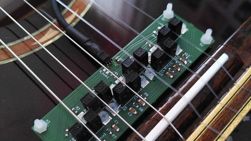
 The concept is simple. You place an LED and a phototransistor in a U-shaped channel, and place it so that the string runs through it. You repeat this for each string. Thus, as a string vibrates, it interrupts the light travelling from the LED to the phototransistor. This generates a voltage that varies with the frequency of the string’s vibration. Funnily enough, this type of pickup will work just fine on both nylon and steel strings, if you were so inclined to try it.
[Simon] designed a nifty PCB with six LED-phototransistor pairs (using off-the-shelf interruptor sensors) for use with a nylon-stringed guitar. He reports that sound from the strings comes through clearly, but that there is some noise that is evident in the pickup’s output, too. Listening to the demo, it seems to capture the sound of the nylon strings well, it’s just a shame that the noise floor is so high.
If you prefer your guitar pickups to be the regular magnetic kind, you can always wind your own from scrap. Demo after the break.


Maybe having two pickups per string in antiphase would get rid of some background noise?
I believe that’s vaguely how humbuckers works?
Yes! https://www.stringkingworks.co.uk/single-post/2019/11/28/humbuckers-polarity-and-phase
I disagree. Humbuckers cancel the hum, not a noise floor. A second set of pickups would not produce the same noise floor, and their anti phase would not cancel or. It’s the same reason why you can’t record two out-of-phase copies of a mono signal on a stereo cassette and cancel out the tape hiss. The noise on each channel is independent.
In an electrical circuit, having two sensors instead of one doubles up the noise _power_ but since power is the square of voltage, the absolute noise amplitude doesn’t double. Meanwhile, the signal amplitude does double, so the signal to noise ratio improves.
The Humbucker setup does improve both measures: it cancels out the common mode error that is picked up by both sensors, and it reduces the noise floor slightly by doubling the signal amplitude while the uncorrelated noise amplitude only increases by a factor of 1.414…
And here we’re talking about the RMS amplitude. For two or more random signals centered around zero, adding them up can sometimes result in double the value, but the probability of that happening goes down with the number of signals you’re adding, so the average noise value goes down.
I’ve spent so much time trying to get those sorts of interruptors to behave properly as digital inputs that I didn’t consider that the analog nature of the phototransistors could actually be a *feature*.
I’m sure the noise floor is high from an audiophile/professional recording standpoint but so are a lot of conventional electric guitar setups. I’m amazed it works so well. Kudos to [Simon!]
I’ve used one as a displacement sensor by placing a small knife edge on a long lever, so when the lever goes up and down the edge interrupts the beam. The beam is only about a millimeter wide, so the lever was used to increase the range to about 10-15 mm. Think of a piano key – you modulate the IR emitter brightness with an oscillator for the sound and then gate and control the volume with the knife edge.
The biggest problem is that the IR LED needs quite a lot of current. You can make it work with less, but the current transfer ratio is only about 10% – that is, for every 10 mA you put through the diode, 1 mA goes through the phototransistor. The actual signal you’ll be working with, or I was, is in the microamps, as most of the current through the circuit is just for the “carrier”.
The transistor acts like a light controller current source (or a “valve”), so you add a resistor in line to turn the current into a voltage signal you can amplify. To get amplitude out of it you need a large value resistor and that adds noise – as the guy notes. To get around that you need to pump more current into the IR diode, but that wastes your battery.
The actual circuit you need for amplifying the signal is called a transimpedance amplifier. An example can be found here:
https://en.wikipedia.org/wiki/Transimpedance_amplifier
The feedback resistor Rf needs to be large to have enough gain, but that is again what creates the thermal noise. Apparently you can get around that by some clever FET pre-amplifier circuit, but I’ve never gone down that rabbit hole.
Though reading the wikipedia article again, it says: “For a good noise performance, a high feedback resistance should thus be used.” – because the gain increases more than the noise. That contradicts what I just wrote.
I can’t see the circuit the guy used, so I can’t comment on what compromises he had to make, but it sounds like there might be a better way to do it.
Right. Saw the circuit, it’s a non-amplified resistor current to voltage converter.
Here’s what I’d try. This circuit is the basic transimpedance amplifier added with a current source that cancels the average current passed by the phototransistors, so the amplifier only amplifies the AC portion of the signal. It takes a while to “warm up” though, so you don’t see the output immediately. You can parallel as many gates as you want to the same amplifier input, because the feedback auto-adjusts for the common mode current, which also means you can tweak the volume of the individual strings by adjusting the LED currents without changing any other component values.
https://tinyurl.com/yqvhwga5
The average current feedback circuit takes the output of the amplifier and puts it through a low-pass filter, and that signal then opens an NPN transistor that lets current back to the input, so if the output tries to rise up above the reference voltage point, it feeds current back towards the optical gates to kill the offset.
I wonder if there any 60Hz hum from ambient light, or a problem with environmental light swamping the signal. If so you might also want to try a chopper amp set up, where you modulate the LED at a frequency well above hearing and then demodulate to extract your desired signal from the receiver.
These gates are pretty well filtered for light other than what comes out of the LED (“daylight blocking filter” says mine), and modern light bulbs emit hardly any IR, and the guy has a plastic cover over the pickups.
That was meant for C. Scott with, “I wonder if there any 60Hz hum from ambient light”.
An IR diode needs only about 1V. So you could connect all 6 in series and use a 9V battery or a 2s LiIon pack.
Slightly more, between 1.1 – 1.6 Volts depending on the part. It might just work on a 9 Volt battery, but you have to account for the fact that the voltage will go down to about 6 Volts when the battery is empty and you still need to leave some headroom for current regulation.
Neat, what about light interference with the pickups? Now if you’ll excuse me I have to go play Smoke on the Water on a fishing pole.
Maybe mounting the pickups sideways would work better as when you strum it vibrates the string in a horizontal direction instead of a vertical one as he has shown.
The string does not vibrate only in the strings plane (parallel with the guitar face). Sometimes it’s a circular vibration. There are needed two sensors at 90 degrees. If there’s space enough.
That and a low pass filter would do wonders.
i came here to say this. the sound must be quite thin with only one sensor per string, summing the output of two would be more realistic
that plus taking measures to mitigate the self noise would fix the floor
Maybe a little less than 90 so there’s a slot to feed the string into?
you could just string through the hole. not an issue
Or tilt one sensor 40 degrees up and the other 40 degrees down, which still leaves you with a small gap.
place them a few millimeters apart and you can even use stock sensors.
If you put your finger in front of a table lamp, and cast a shadow an equal distance away on a piece of paper, you’ll notice that the shadow has a fuzzy halo and it’s not quite dark in the middle. When you bring your finger closer or further away from the paper, you’ll notice that the shadow gets darker and lighter.
So in fact, the pickup does work in both planes!
The string vibration isn’t confined to a single plane. It’s neither vertical nor horizontal: It’s a combination of both.
So, a better idea would be to mount TWO pickups! Vertical and horizontal!
You could probably do some pretty cool effects by using the phase different as an input to some filter control or something
While a great experiment and certainly a learning exercise, maybe simplest is best and go back to basics with a piezo pickup for practicality?
It sounds pretty good to my ears! Even piezos and microphones pick up noise, especially live, on stage. I speculate that if these optical pickups were shielded from ambient light, the noise floor would be lower. Think of this as a proof of concept. Experimenting with higher quality photodiodes, the results might get quieter. These cheap photo-interrupters are not optimized to deliver high-quality audio. Lastly, these are oriented so they mostly pick up vertical vibrations (perpendicular to the body). That’s not the dominant vibration axis. LEDs above the strings and photodiodes parallel to the PCB might work better. Sally forth!
I didn’t hear any 60Hz hum, so I think we can rule out noise from the ambient lighting. Humbuckers reduce induced noise from external signals, so that type of setup isn’t going to help.
He runs the thing of 9V – the first thing I would try is reducing the voltage. This would allow the current-limiting resistor on the LED to be reduced in value, as well as any biasing resistors on the phototransistor. Less resistance = less thermal noise, which from the sound of the demo seems to be at least part of the issue. A better-quality phototransistor would likely also help – especially one intended for analog signals rather than digital.
Ok to me I love the sound as a feature. It reminds me of old time records. Damn!
Can you post the schematic for that! I suck at making things and just learning guitar but that is definitely something I would like!
The schematic is in https://codeberg.org/Luno/KlimperLux as a file for kicad
It would be interesting to try driving the LEDs at a high frequency and then obtaining the audio with an amplitude modulation detector.
My thoughts exactly — you beat me to it. A bandpass filter at the “carrier” frequency should eliminate any power-line “light hum” sources, too.
I’ve done some experiments back in 2008 with a similar setup. It seemed to work really well. For a short while I thought I have actually invented something, until I found out about Ron Hoag, who had this idea back in the late ’60s :)
There is no filtering due to inductance and capacitance of the windings, that we are used to on the magnetic pickups, hence we end up with an unusually bright and detailed sound.
Just FYI this is called a lock-in amplifier and it’s a pretty good idea :)
Well it sounds fine to me ! but I don’t know anything about guitars, music or acoustic , I was wondering if you can improve it by using permanent black marker to paint all the sections of the strings that go between the sensors and maybe removing the plastic hat of the photo-transistor as I assume it was designed for switching.
Maybe a noise gate could dampen the hiss.
They should use a lock in amplifier setup. Modulate the LEDs at several MHz and demodulate the result.
DIY FTW! https://www.willcoxguitars.com/lightwave-optical-pickup-system/
The strings don’t vibrate in a single plane; they could be any angle or circular.
So, figure out the string location by using two optocouples. If they are coincidental, you might get sound out. But any distance between the measurement points, and I feel like the math required would end up being frequency dependant. Which negates the goal of finding the frequency.
Well, I even think even a centimeter of distance between the optocouplers should be negligible as the wavelength of the strings are comparatively long.
you might be able to get rid of some noise simply with a little optical isolation.
ive been doing a new set of joystick grips and opted for an optical sensor for the analog trigger. just using a photodiode and a resistor i can get about 2 volts of range, which is fine, i could amplify that but i dont think its necessary for a trigger. but i did design the thing with an optically isolated compartment, where there is a slit and wedge arrangement and the noise is minimal. you could probably just print a cover to block out any stray ir. some isolation between the sensors would also be a good idea.
I guess I don’t know what’s going on here, but in my experience, nylon is transparent to IR. …and to add, a vibrating string’s excursion is not necessarily normal to the light axis in this application.
What about the frequency response?
Noise is high because of wrong components values. The 100pF capacitor is definitely too low for audio. The result is a very low output signal that forces to crank up the input gain in the amplifier/audio card, which in non professional gear usually translates into high background noise. The 100nF caps also are too low, I would change them as well and use min 1uF poly capacitors everywhere in the signal path.
Also, the 10uF cap on the left should be connected between the junction RV1/2 + R1/2/3 etc. and ground, not before RV1/2; this way it works as a decoupling low pass filter wrt the noise coming from power supply. RV1/2 can be a single resistor, no need to parallel two. To reduce current draw, emitting diodes can be put in series in groups of 2 or more according to the power supply voltage, so that their series resistor can be recalculated to dissipate less current.
Why are people hypothesizing about the sound in the comments?
Do commenters not believe that the attached audio file is real?
Certainly someone will correct me but I think the first electric guitars were made by putting a phonograph needle onto each string. Those work in 2dimensions.
This project is possibly witnessing the birth of something like that.
.
My advice. File a provisional patent immediately even if, or especially if, you have no intention of commercializing. In US it’s “first to conceive” but I can tell you this will get ripped off immediately if it isn’t already. Again I know not a lot about guitars but if this rally is the innovation it seems like then take the IP. Now.
Americans.. Patents, lawsuits and super capitalism.. 🙄😂
But anyway, speaking of patents, there’s also something called “utility model protection”.
It might be an alternative. I’m just a layman, too, though.
So if the idea isn’t being “worthy” enough for a patent, this might be an alternative.
It’s about the practical application of a certain invention.
I’m saying Lightwave probably patented this years ago. This is not new technology.
https://www.willcoxguitars.com/lightwave-optical-pickup-system/
https://www.willcoxguitars.com/lightwave-optical-pickup-system/
Our patented infrared light technology is the first and only of its kind. The pickup “sees” the vibration of the string without affecting string motion in any way, harnessing the pure power of light to deliver accurate, full-range sound.
This tech has been around for years.
It is funny how many comments there are saying it _needs_ this and that when there’s a demo clip that shows that it clearly works just fine.
By the way, this also works with, say, 1920s technology, no need for fancy semiconductors.
A selenium cell and an miniature incandescent lamp (for doll houses or model making) will do.
Early lightphones worked by same principle, they used ordinary light bulbs/ incandescent lamps.
People are hilarious. They will spend a fortune on pickups then plug the instrument straight into a distortion pedal
One reply mentioned ‘carrier’. That is a concept to follow-up. Add a high frequency to modulate with the string’s movement. Detect, demodulate, filter, amplify. 90 degrees good too.
Lightwave designed this years ago. (Dr. Shock!!!) I played a Zon bass with this pickup system as my main axe for years. To touch on a couple things mentioned in other comments:
– yes, light pollution is a problem, specifically flash photography. A good dose of it makes a big POP come out of your amp. I applied liberal amounts of gaff tape for wedding gigs
– it is the cleanest quietest pickup system I’ve ever used by a WIDE margin. This design is capable of near silent operation with a huge signal to noise ratio
– Yep, focusing / aligning the sensors on the string is a necessary act. I used “taper core” strings (maybe required) where just the core of the string is in front of the sensor, so all the strings are (relatively) the same size
– It’s a little overcomplicated to have a separate preamp for each string, but that was the design. Felt like I never had it perfectly dailed, like one string was always a little louder or too dim — between string alignment and a separate volume trim pot for each string, it was pretty fiddly
– The low frequency information is reproduced so cleanly. Never had a more godlike B string in my life
Great work [Simon]!
great work [Simon]! I’m a classical guitarist and tinker a lot with different pickups and such. I liked the sound you got quite a bit. One consideration is that your pickup only captures the vibration in one plane (up and down relative to the guitar), but the string is vibrating in every direction (left/right, up/down, around…).
maybe a simple mirror/optical arrangement could be done to capture more than one direction using a single sensor, string only vibrates in one direction at any one instance.
looking forward to more on this one
You can still use nylon string with a normal magnet pickup .My solution to using nylon strings is to find some stainless steel tubing, like 17-4. Mcmaster carr sells a lot of this stuff. Find the right ID of tubing to the particular string and bond them with epoxy. You want to center SS tube over the pick up. It may only need an inch of tubing per string.
How about wrapping a tiny ferrule around the string and using a normal pickup? :D
I wonder if changing the LED for a different color one might affect the sound in any significant way…
That way you could really play the blues!
Use 2, one on each axis, run it into an OP amp, anlog filters, then to an ADC, then to a microcontroller, do some fancy math, add some input controls and do signal processing.
OR, and a big OR, use a magnetic pickup and make life easy
That sounds pretty good. I’ve been working on my own version of an optical pickup for a few years now (part time) and the above results have encouraged me to give it a higher priority. I’m using an off the shelf infrared sensor – combined with multi stage opamp filters (per string). My goal is to have a system that runs off 3V (a single AA battery pumped up to 3V) and have each string processed separately and fed into a ARM micro – that way I can use it to pitch detect and produce midi output for each string. I think the possibilities for this are endless. My only concern is that there seems to be patents that try to claim that the idea of an optical pickup for a stringed instrument is their sole creation and that no one is allowed to innovate in this area from now on. The concept of using optical pickup for a stringed instrument is an old one, and people should be allowed to create better versions if they are able.
How is your project coming along? Would you be willing to share your insights on this? I play touch instruments, so highly interested myself into going that route. Especially because when you tap instead of strum, the string vibrates in one plane exclusively. Only thing, I am scared of designing the electronic myself…
I’m not a musician, but this is a useful discussion that can be applied to all sorts of motion sensing. Seismometers, DIY joysticks, automotive etc. Nice work.
So much concern over the 2D motion of a string and not picking up both. Both a contact mic and a normal pickup don’t have a problem with only 1D string vibration, neither does a bridge and soundboard. If you could pick up both motions with separate pickups you would either have to mono them which would exaggerate the phase differences and possibly get more inharmonicity than normal or do stereo which would not do much sometimes being out of phase. Sort of a stereo phasor effect, not normal sound. There is also the longitudinal vibration which rocks the bridge and produces two out of phase vibrations of the single soundboard. It is a single function which is the bulk of the sound of any soundboard-bridge-string combo.
So don’t worry about it. Picking up the sound is not picking both vibrations of the string, it’s the whole thing’s sound. Hear is an idea to try. Make a pickup which is tension based not lateral vibration, as in a strain gauge. There will be a difference. Meanwhile I bury a condenser mic element in the bridge and let these complex motions get scaled to mono.
when i went down this road about 15 years ago i found there was a very nice Canadian man who had pretty much perfected this some time around late sixties early seventy’s.
i am trying to find his info i do think he is deceased now. i found him while doing my own research and he had a website stating he would build you a scratch guitar with his system in it for around 600usd.
i jumped on it and when we talked he said he actually couldn’t tell me much about it anymore and couldn’t build me anything as he had sold his patent to a company and they were going on into production.
He was a very nice and knowledgeable man he did however point me into the right direction by letting me know his patent was searchable online. also he he said if you are using it on electric guitar you should ad an inductor to give that snap like an electric guitar had or it can sound a little unnatural.
i ended up abandoning my light pickup and instead started building light based boost pedals.
couldn’t find a backer at the time and my pedals been on the shelf till late last year when we started production again.
that being said this is not meant to detract from the information presented here friend you have done well and articulate work i wish you nothing but success
Is that not how the Lightwave Guitar pickups work and would have an associated PCB that would be inside the body of the guitar that would connect to the amplifier via a power interface as they would be hard on the battery, don’t flash this about to much as I think that there is a copyrite design