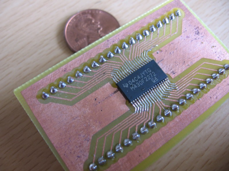
We got a hold of some DS3232 RTC chips in a 20-pin SOIC package. We’d like to have one that is breadboard compatible for easy prototyping but when we searched for SOIC20W breakout board artwork we found none. We used Eagle to design our own and you can see the finished product above which we made using the toner transfer method and cupric chloride.
You’ll find the artwork after the break in case you need to make your own breakout board some day. If you know of surface mount breakout board artwork that is freely available please leave the link in the comments for future use, or send it to us on our tips line and we’ll add it to the post.
Incidentally, the DS3232 is the same as the DS3231 used in the ChronoDot but with the addition of some SRAM. We’ll let you know if we come up with an interesting project for it.
Update: We added 28 SSOP to DIP artwork submitted by [Paul Dekker]
20-PIN SOIC to DIP

28-pin SSOP to DIP [Thanks Paul Dekker]


Its not particularly hard to design or make the breakout boards in Eagle, just drop a generic package and wire pads to header pins. It is however really tricky to squeeze some packages into standard socket sizes to act as drop-in replacements for DIP socket components (eg: an opamp)
@aonomus: I had a tough time finding a part in Eagle that uses the SOIC20W package and also uses all of the pins. On the DS3232 there’s a bunch of pins with no connection but I wanted to design one breakout board for the footprint, not a chip-specific design. This is why it would be convenient to have a collection of artwork for each type of footprint.
On toner transfer there is an outfir in the US called pulsar who do a great product
http://www.pulsarprofx.com/PCBfx/main_site/pages/index.html
I used it years ago , i see you can get it from digikey now too, worth a look for hackertypes.
The Idea is really old:
http://www.mikrocontroller.net/articles/SMD_2_Steckbrett_Adapter
@Luky: Of course the idea is old — people have been doing breakout adapters forever. The real question, however, and the benefit here, is whether there exists a library of these parts already and that here’s an actual working board for a 20SOICW specifically.
I’ve made a few similar boards, and they are definitely handy. Good practice for learning toner transfer and SMT soldering as well…
Funny I was just in the process of making one of these for the TL494 chip
I much prefer photo etching the pcb’s
@Mike – It’s fairly easy to create device parts in eagle, trivial if the land pattern already exists in another part. Land patterns exist separately from devices and are pin-mapped to them to create parts in various technologies. Thus a 555 timer has once device schematic but can be laid out in dip or soic etc.
What you need to do is create a generic 20 pin device “Mike 20 pin”, then find the 20pin soic technology and pin map them together.
http://www.sparkfun.com/commerce/product_info.php?products_id=495
I for one would really be interested in a guide how to create, prepare and etch a board for TSOP-dense chip. What I have found out is that 600dpi printer just don’t cut it for such small traces (0,2mm pad, 0,3mm spacing..).
doing a breakout board is a good start to practice smd-soldering and etching. it’s about the easiest board possible but it is not just a test board, so at least I wouldn’t fell like wasting time.
the next step of course would be to add a couple parts to a breakout board and call it an arduino..
I’ve had very good results using home-etched PCBs to build small “modules” that combine a few SMD parts into one usable unit, and sizing the unit so that it fits in a breadboard.
If the module’s pin spacing is 0.9″ or smaller it will fit in any breadboard, if it’s larger you can still use it by making it straddle one of the power rails.
I’ve made lots of them (oscilloscope input stage, signal generator, motor drivers). I should write up an article. ;)
what about this design with a female header on top mapped to the male headers on the bottom, so for prototyping, you simply use jumpers to chose your outputs. or am i just tooting my own whisle?
I made a breakout board generator in OpenSCAD about two months ago. Just pass it the parameters that describe the package type you need a breakout board for and let OpenSCAD do the boring work for you..
http://www.thingiverse.com/thing:1904
I just order mine from Futurlec. They have slow delivery, but are very cheap.
http://futurlec.com/SMD_Adapters.shtml
Hello to all
today I made so8 to brakout board conversion :)
here you can see the final product
http://www.sargonout.sk/so8.jpg
IC is max6675
k-type thermocoupler to spi convertor
I recently stumbled upon this site:
http://www.proto-advantage.com/store/index.php
They have dozens of different SMD to through-hole adapters. Check ’em out if you don’t want to make your own!
How about something that will let me swap op amps on my sound card which is pretty much all SMT, with viciously small pitches at that …
The Artwork is very nice but kinda useless, for those of us that would like to just print out the artwork. How would one scale it down to real size? If I just Print it comes out covering a 8.5 x 11 page.
Where is the Eagle schematic that i could deal with.
Thanks,
Ralph
http://www.imajeenyus.com/electronics/20110805_smd_adapter_boards/index.shtml
just came across these how do i print them with out them being a whole 8.5 x 11 page