Prototyping The Prototype

For basic prototyping, the go-to tool to piece together a functioning circuit is the breadboard. It’s a great way to prove a concept works before spending money and time on a PCB. For more complex tasks we can make use of simulation software such as SPICE. But there hasn’t really been a tool to blend these two concepts together. That’s what CRUMB is hoping to solve as a tool that allows simulating breadboard circuits.

Currently, most basic circuit functions are working for version 1.0. This includes passive components like resistors, capacitors, switches, some LEDs, and potentiometers, as well as some active components like transistors and diodes. There are some logic chips available such as 74XX series chips and 555 timers, which opens up a vast array of circuit building. There’s even an oscilloscope feature, plus audio output to incorporate buzzers into the circuit simulation. Currently in development is an LCD display module and improvements to the oscilloscope.

Besides prototyping, this could be useful for anyone, students included, who is learning about circuits without the need to purchase any hardware. The major downside to this project is that it there doesn’t seem to have a free or trial version, the source is not available, and it’s only for sale on Steam, Apple Store, and Google Play. That being said, there is a forum available for users to discuss problems and needs for future versions, so it’s possible that a community could build up around it. We’ve seen previously non-free versions of circuit simulation software become more open after some time, so it’s not out of the realm of possibility.

Thanks to [Thomas] for the tip!

Several shelf boxes of various widths are held together by brightly-colored plus-sign-shaped connectors.

3D Printed Shelf Connector

Sometimes, you really need a custom shelf. Whether you have a weird-shaped space, weird-shaped stuff, or just want something different, making your own shelving can make your place more like home. The Plus Shelf by [shurly] aims to make building your own shelves a little easier with a 3D printed bracket.

These connectors aren’t just sitting flush against the wood of the shelf. Each end of the + sign actually sits in a 3/8″ drilled recess, giving a more secure fit. The pieces were printed on an Objet and then dyed in various bright shades to really make the shelving pop. The cubbies were assembled with biscuits after cutting down a sheet of plywood to the appropriate sizes. The 45˚ angles around the edges of the cubbies make the whole shelf system that much nicer.

The final shelf has a little wobble, but that’s probably because dying the shelf connectors made them “bendy.” Because of the instability with the friction fit, the shelf connectors were super glued into the shelf boxes. [shurly] hopes that a metal version of the connectors might be able to eliminate these problems in the future.

This shelving system not your cup of tea? Maybe you’d prefer this Vintage Adjustable Shelving Method or this MP3 Player Shelf.

KachiChan_Sisyphus_RobotArms-On-A-Platform

Robot Repeatedly Rearranges Remnants In The Round

Sisyphus is an art installation by [Kachi Chan] featuring two scales of robots engaged in endless cyclic interaction. Smaller robots build brick arches while a giant robot pushes them down. As [Kachi Chan] says “this robotic system propels a narrative of construction and deconstruction.” The project was awarded honorary mention at the Ars Electronica’s Prix Ars 2022 in the Digital Communities category. Watch the video after the break to see the final concept.

KachiChan_Sisyphus_RobotArms-On-A-Platform_detail-view

[Kachi Chan] developed the installation in pre-visualizations and through a series of prototypes shown in a moody process film, the second video after the break. While the film is quite short on details, you’ll see iterations of the robot arm and computer vision system. According to this article on the project [Kachi Chan] used Cinema 4D to simulate the motion, ROS for control, PincherX150 robotic arms modified with Dynamixel XM 430 & XL430 servo motors, and custom 3D prints.

We’ve covered another type of Sisyphus project, sand tables like this and the Sisyphish. Continue reading “Robot Repeatedly Rearranges Remnants In The Round”

Injection Molds: Aluminum Or Resin?

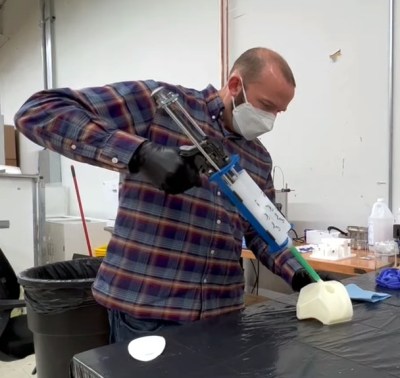
[JohnSL] and his friend both have injection molding machines. They decided to compare the aluminum molds they usually use with some 3D printed molds created with a resin printer. They used two different resins, one on each side of the mold. You can see a video of the results below.

One half of the mold used ordinary resin while the other side used a resin that is made to hold up to higher temperatures. As you might expect, the lower-temperature resin didn’t stand up well to molten plastic. However, the higher temperature resin did somewhat better. It makes sense, though, that an aluminum mold draws more heat out of the plastic which is helpful in the molding process.

The higher temperature — and more expensive — resin did seem to hold up rather well, though. Of course, this was just to test. In real life, you’d want to use the better resin throughout.

No surprise, the resin molds didn’t last nearly as long as a proper mold. After 70 shots, the mold was worn beyond what you’d want to use. So not necessarily something you’d want to use for a real production run, but it should be enough for a quick prototype before you go to the expense of creating a proper mold.

We wonder if there are some other tricks to get better results. A comment from [TheCrafsMan] suggests that clear resin UV cures better, and that might produce better results. In fact, there are a lot of interesting comments on the video from people who have varied experiences trying to do the same thing.

If nothing else, watching the mill cut through the aluminum around the 15-minute mark is always interesting to watch.  If you don’t already have an injection molding setup, you can always build one. We’ve seen more than one design.

Continue reading “Injection Molds: Aluminum Or Resin?”

Laser Z-Axis Table Comes Into Focus

Laser cutters and 3D printers are game-changing tools to have in the workshop. They make rapid prototyping or repairs to existing projects a breeze as they can churn out new parts with high precision in a very short amount of time. The flip side of that, though, is that they can require quite a bit of maintenance. [Timo] has learned this lesson over his years-long saga owning a laser cutter, although he has attempted to remedy most of the problems on his own, this time by building a Z-axis table on his own rather than buying an expensive commercial offering.

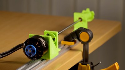
The Z-axis table is especially important for lasers because a precise distance from the lens to the workpiece is needed to ensure the beams’s focal point is correctly positioned. Ensuring this distance is uniform over the entire bed can be a project all on its own. For this build, [Timo] started by building a simple table that allowed all four corners to be adjusted, but quickly moved on to a belt-driven solution that uses a stepper motor in order to adjust the entire workspace. The key to the build was learning about his specific laser’s focal distance which he found experimentally by cutting a slot in an angled piece of wood and measuring the height where the cut was the cleanest.

After everything was built, [Timo] ended up with a Z-axis table that is easily adjustable to the specific height required by his laser. Having a laser cutter on hand to bootstrap this project definitely helped, and it also seems to be an improvement on any of the commercial offerings as well. This also illustrates a specific example of how a laser cutter may be among the best tools for prototyping parts and building one-off or custom tools of any sort.

iPod Prototype

IPod, Therefore I Am: Looking Back At An Original IPod Prototype

Have you ever wondered what consumer electronics look like when they’re in the ugly prototype stages? So have we. And thanks to [Cabel] of at Panic.com, we have a rare glimpse at a prototype first generation Apple iPod.

In the days before you could just stream your favorite music directly from your phone and into your Bluetooth speaker, pods, or car, there was the Sony Walkman and various portable tape players. Then there were portable CD players. As MP3’s became a popular format, CD players that could play MP3’s on home made CD’s were popular. Some portable digital media players came to market in the mid 1990’s. But in October of 2001, the scene changed forever when Apple unveiled the first generation iPod.

Of course, the iPod didn’t start out being so svelte, shiny, and downright cool. This engineering prototype has been hiding in [Cabel]’s closet for almost 20 years and they’ve just now decided to share with us its hilariously oversized case, JTAG port, and square pushbuttons that look like they came from a local electronics supply house. As [Cabel] brings out in the excellent writeup, the hardware itself is very close to production level, and the date on the prototype is very near the actual product launch.

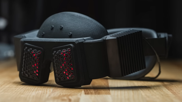
Of course prototyping is an essential part of building any product, production or otherwise. Having a gander at such pre-production devices like this, or these off-ear speaker prototype for Valve’s VR headset reminds us just how important even the ugliest prototypes can be.

Have you got any pre-production nuggets to share with the world? Be sure to let us know by dropping a note in the Tip Line, and thanks to [jp] who sent this one in!


Chipboard prototype of a wireless phone charger with style.

Prototyping Your Way To Better Prototypes

If you’ve ever made a prototype of something before making the “real” one or even the final prototype, you probably already know that hands-on design time can’t be beat. There’s really no substitute for the insight you will glean from having a three-dimensional thing to hold and turn over in your hands for a full assessment. Sometimes you need to prototype an object more than once before investing time, money, and materials into making the final prototype for presentation.

This is [Eric Strebel]’s second video in series about making an eco-friendly wireless phone charger. He made a paper prototype in the first video, and in this follow-up, he refines the idea further and makes a chipboard version of the charger before the final molded paper pulp prototype. The main advantage of the chipboard version is to design the parts so that each one will be easier to pull from its mold in a single piece without any undercuts.

By building the chipboard version first, [Eric] is able to better understand the manufacturing and assembly needs of this particular widget. This way, he can work out the kinks before spending a bunch of time in CAD to create a 3D-printed mold and making the paper pulp prototype itself. He emphasizes that this process is quite different from the 2.5D method of laser-cutting a single piece of chipboard and folding it up into a 3D object like it was a cereal box, which is likely to hide design issues. Be sure to check out the video after the break.

We think this prototype is quite nice-looking, and believe that everything deserves good design. Why should a wireless charger be any different? [Eric] has prototyped in a lot of media, but he seems especially skilled in the art of foam core board. Start with the masterclass and you’ll have a better appreciation for his foam armored vehicle and one of the many ways he smooths out foam parts.

Continue reading “Prototyping Your Way To Better Prototypes”