FPGA Breakout Board For DIP Package Shenanigans

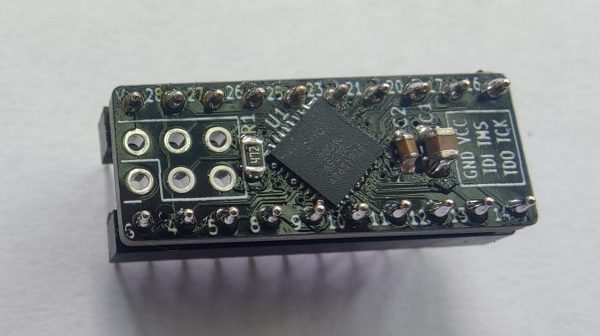
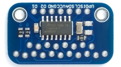
FPGAs are supremely flexible and powerful devices. However, they usually come in QFP or BGA packages that are altogether difficult for hobbyists to play with. The DIP-FPGA breakout board aims to solve that problem by using a carrier PCB to put an advanced chip in a friendlier form factor.

The board itself fits a DIP-20 form factor when soldered up with regular-pitch pin headers. It features a  MachXO2-1200HC FPGA from Lattice Semiconductor. That’s the same chip as used on similar the TinyFPGA A2. With 18 GPIO, a DIP-20 layout is just about enough pins to take care of business. It’s intended specifically for use on breadboards or via regular IC sockets. There’s also a six-pin programming port laid out on the board that you can use with pogo pins or header connectors as you desire.

If you want to do some fancy signal stuff in an easy-to-prototype form factor, this could be the setup for you. If you want to buy one ready-made, they’re available on Tindie for the curious. In the meantime, consider whether this beefy FPGA Arduino concept could also propel your next project to greater heights.

A Handy Breakout Board For E-Paper Hacking

If you follow the exploits of [Aaron Christophel] (and trust us, you should), you’ll know that for some time now he’s been rather obsessed with electronic price tags, specifically those with e-paper displays. It’s certainly not hard to see why — these low-power devices are perfect for ambient displays, and their integrated wireless capabilities mean you can put one in every room and update them from a central transmitter.

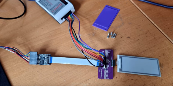
But with such a wide array of products on the market, [Aaron] has found himself doing a lot of e-paper reverse engineering. This involves sticking a logic analyzer between the display and the tag’s microcontroller, which he found to be a rather finicky task. That’s why he created the Universal E-Paper Sniffer: a breakout PCB that lets you snoop on display communication without having to resort to unpleasant methods like scratching off the solder mask to tap into the traces by hand.

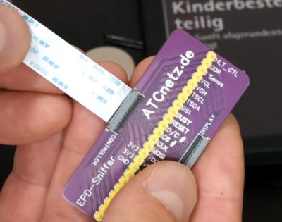
It’s a pretty simple gadget: on either side, you’ve got a connector for 24 pin 0.5 mm pitch flat flex cable, which [Aaron] has identified as the most common interface for these displays, and in the middle you’ve got a standard 2.54 mm pitch header. There are no other components on the board, and all the traces go right through to the other side.

Add a few jumpers and a cheap logic analyzer, and you’re ready to sniff some SPI commands. Check out the video after the break for a general walk-through of what it looks like to start sniffing around a new display.

The Gerber files for the breakout are available for free, or you can chose to buy a fabricated board through PCBWay to kick [Aaron] a portion of the sale price. However you get one, we think this will be a handy little tool to have around if you find yourself bitten by the price tag hacking bug.

Continue reading “A Handy Breakout Board For E-Paper Hacking”

Universal TFT Display Backpack Helps Small Displays Shine

TFT technology might be ancient news for monitors and TVs, but it’s alive and well when it comes to hobbyist electronics and embedded devices. They’ve now become even easier to integrate, thanks to the Universal TFT Display Backpack design by [David Johnson-Davies].

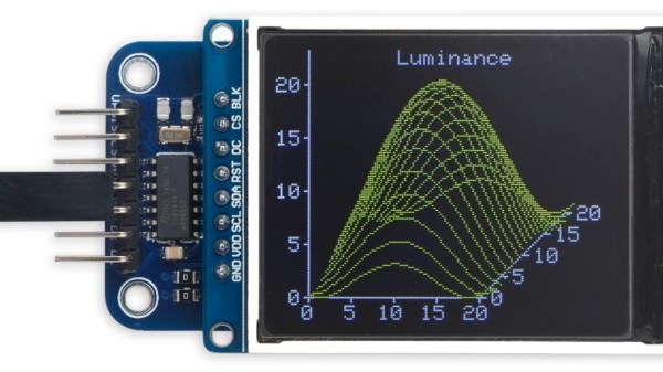
Breakout board, compatible with pinouts of most small TFT displays.

Such displays are affordable and easy to obtain, and [David] noticed that many seemed to have a lot in common when it came to pinouts and hookup info. The result is his breakout board design, a small and easy-to-assemble PCB breakout board that can accommodate the pinouts of a wide variety of TFT displays available from your favorite retailers or overseas sellers.

The board has a few quality-of-life features such as an optional connection for a backlight, and a staggered pin pattern so that different TFT boards can be pushed in to make a solid connection without soldering. That’s very handy for testing and evaluating different displays.

Interested? Head on over to the GitHub repository for the project, and while you’re at it, check out [David]’s Tiny TFT Graphics Library 2 which is a natural complement to the display backpack. [David] sure knows his stuff when it comes to cleverly optimized display work; we loved his solution for writing to OLED displays without needing a RAM buffer.

SMD Breadboard Adaptors Skip Schematic, Goes Straight To PCB

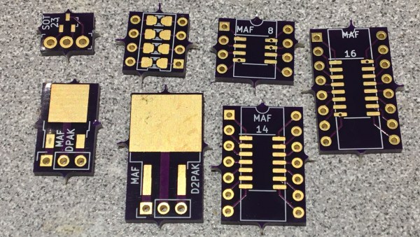
If you need to add one or two SMT chips to your breadboarded prototype, [Travis Hein] has you covered. He designed a set of small SMD adaptor boards for various SOIC, SOT23, and DPAC patterns using KiCad.  He has released them as open source, so you can feel free to use them or modify them as needed.

Normally we don’t see people bypassing the schematics when designing a PCB. But we can agree that [Travis] has found a situation where going direct to PCB makes more sense. He just plops down the package in Pcbnew, adds some pin headers and wires everything up directly on the PCB. (But don’t worry, some of you may remember [Travis] from his earlier SSR mains switching project, which demonstrates that he can indeed draw proper schematics.) We know there are more people out there who prefer to go straight to PCB layout… [mikeselectricstuff] comes to mind. If you could yourself among this tribe, let use know your reasoning in the comments below.

We wrote about a similar universal breakout boards for SMD parts back in 2016, which is a single breakout board for two- and three-pin jelly-bean components. If you paired some of those boards with [Travis]’s breakout boards, it would make a great combination to keep in your prototyping gadgets bin. Consider this project the next time your favorite PCB shop has a sale.

The Smaller, Tinier Arduino Platform

While many of the Arduino platforms are great tools for gaining easy access to microcontrollers, there are a few downsides. Price and availability may be the highest on the list, and for those reasons, some have chosen to deploy their own open-source Arduino-compatible boards.

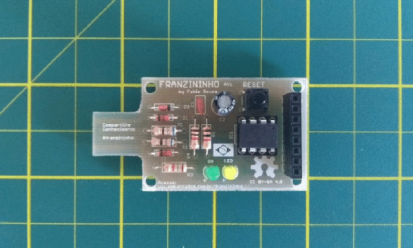
The latest we’ve seen is the Franzininho, an Arduino Gemma-like board that’s based on the ATtiny85, a capable but tiny microcontroller by Atmel in a compact 8-pin configuration. This board has everything the Gemma has, including a built-in LED and breakout pins. One of the other perks of the Franzininho over the Gemma is that everything is based on through-hole components, making the assembly much easier than the surface mount components of the Gemma.

It’s worth noting that while these boards are open source, the Arduinos are as well. It’s equally possible to build your own 100% identical Arduino almost as easily. If you want more features, you can add your own by starting from one of these platforms and do whatever you want with it, like this semi-educational Atmel breakout board.

Thanks to [Clovis] for the tip!

Micro-ATX Arduino Is The Ultimate Breakout Board

If you’ve been hanging around microcontrollers and electronics for a while, you’re surely familiar with the concept of the breakout board. Instead of straining to connect wires and components to ever-shrinking ICs and MCUs, a breakout board makes it easier to interface with the device by essentially making it bigger. The Arduino itself, arguably, is a breakout board of sorts. It takes the ATmega chip, adds the hardware necessary to get it talking to a computer over USB, and brings all the GPIO pins out with easy to manage header pins.

But what if you wanted an even bigger breakout board for the ATmega? Something that really had some leg room. Well, say no more, as [Nick Poole] has you covered with his insane RedBoard Pro Micro-ATX. Combining an ATmega32u4 microcontroller with standard desktop PC hardware is just as ridiculous as you’d hope, but surprisingly does offer a couple tangible benefits.

RedBoard PCB layout

The RedBoard is a fully compliant micro-ATX board, and will fit in pretty much any PC case you may have laying around in the junk pile. Everything from the stand-off placement to the alignment of the expansion card slots have been designed so it can drop right into the case of your choice.

That’s right, expansion slots. It’s not using PCI, but it does have a variation of the standard Arduino “shield” concept using 28 pin edge connectors. There’s a rear I/O panel with a USB port and ISP header, and you can even add water cooling if you really want (the board supports standard LGA 1151 socket cooling accessories).

While blowing an Arduino up to ATX size isn’t exactly practical, the RedBoard is not without legitimate advantages. Specifically, the vast amount of free space on the PCB allowed [Nick] to add 2Mbits of storage. There was even some consideration to making removable banks of “RAM” with EEPROM chips, but you’ve got to draw the line somewhere. The RedBoard also supports standard ATX power supplies, which will give you plenty of juice for add-on hardware that may be populating the expansion slots.

With as cheap and plentiful as the miniITX and microATX cases are, it’s no surprise people seem intent on cramming hardware into them. We’ve covered a number of attempts to drag other pieces of hardware kicking and screaming into that ubiquitous beige-box form factor.

Use All That Extra Space With PCB Panelization

Anyone who’s made a PCB has encountered the conundrum of having to pay for space that you don’t use… for instance, designing a round PCB and seeing the corners go to waste. The solution? Smaller boards added to the blank spots.

One logical stumbling block might be that you simply don’t have a small PCB design ready to go. Latvian hacker [Arsenijs] created a resource of small PCBs that can be dropped into those blank spots, as well as a tutorial on how to combine the gerbers into a single panel.

Great minds think alike, and this guide is following hot on the heels of [Brian Benchoff’s] article on panelization. They’re both a great read. It’s interesting to think that not long ago we would see multiple guides on home etching boards and now we’ve climbed the production ladder to guides that help better utilize PCB fab houses. Neat!

This project seems a logical spinoff of [Arsenijs]’s ZeroPhone Pi smartphone project, a finalist for the 2017 Hackaday Prize that makes a low-cost phone using a stack of PCBs. One imagines that while prototyping the phone [Arsenijs] ended up with a lot of wasted space! Fill that up with smaller designs like breakouts, or decorative items like a hackerspace business card. If you’re looking for small PCBs you can find a few in the files area of the project on Hackaday.io. Otherwise, you can share yours and [Arsenijs] will add them.