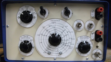
What do you do when you’ve got three broken function generators? Build your own, obviously. Since your workshop has already gone through three of these bad boys, you might find yourself repairing your build. Better not use any fancy ICs and go with a transistor only build.
When [Miroslav] sent in his ‘guerilla homebrew’ square wave generator, we were really impressed. With a relatively simple schematic that uses parts that could be salvaged from old radios, this is a real MacGyver build.
The generator is based around a simple astable multivibrator. It doesn’t provide sine waves, but it’s the easiest circuit to get working. The build started off with a quartet of 2N4401 transistors, but according to the datasheet and the venerable Tektronix 502A, these had a very bad rise time compared to 2N3904s.
[Miroslav]’s project generates square waves up to 2.22 MHz and pulses with a variable duty cycle from 1-49% and 51-99%. Output is either 5 Volt TTL levels or an adjustable 0-3.38 level. The generator is exactly what [Miroslav] needed, so that makes it a great tool in our book.


The guy complains a lot about the front panel manufacturing problems.
I can’t see why he didn’t just put the front plate in a scanner, drew some empty scales on that, and then printed the entire thing at one go instead of cutting all the pieces separately. Mark the spots, scan it back in and clean up the work. The final version could be simply laminated and cut to fit.
Whatever floats his boat I guess.
I personally don’t get it. It seems like an awful lot of polish on what amounts to a really primitive piece of test equipment.
Its a great looking front panel and unit overall. Extremely limited functionalty though. Whenever I need square pulses I just grab a microcontroller development board and pulse a pin. I even get <10ns rise times. Seems like the internals don't live up to the fancy exterior.
I don't see the point of nostaligia at the expense of performance and usefulness. Considering this thing ONLY does pulses you'd expect the rise times to be good. Would be useful for testing the bandwidth of oscilloscopes. 40ns is pretty pathetic.
Seems like it'd be pretty easy to keep the case and replace the internals with something more useful though. My suggestion would be a DDS chip with microcontroller which can give you sine, square, triangle, sawtooth etc.
Of course today there is no point in designing a transistor only generator if you have handy a chip that does all that with minimum part count, but if you look at it as a tool to teach electronics it shows its great value.
Learning electronics basics on specialized chips is like learning programming (or pretending to) by dragging components on a Visual Basic form.
Transistors in that context are better because they represent the smallest atomic part you can use to build a circuit function.
As a tool to learn electronics it wastes to much effort on the exterior. As a tool for generating pulses, its just by no means good enough for many applications requiring pulses.
I don’t understand why some of you are so focused on the specs of this thing. It’s plainly got a dedicated shop use and is a perfect example of appropriate technology.
Further, I find it much quicker and easier to use the old Datapulse I bought off ebay as test equipment than brew something up with a micro or 555 timer or whatever. If I didn’t have one, I’d probably build something like this. It used to be a fairly common project to add all the knobs and switches and jacks to a 555 timer that you’d need to make a piece of test equipment out of it.
Nice features from the datapulse he might want to think about adding:
1) It has external gating and triggering, with an adjustable pulse delay
2) It has a single pulse (one-shot) mode with a pushbutton trigger
He’d end up using more than four transistors though!
Thanks for your comments.
I like the idea of printing the whole front panel at once. I might try this next time. It will possibly save a lot of time.
Device is definitely limited: but in some respects less so than devices it replaced. Frequency range is much wider, fine tuning and pulse generation is possible, etc. Even sine wave can be had by connecting an RC filter accross the output.
I make no apologies for simplicity: 40 pin chips soldered to the randomly found board, without datasheets, are useless for those who have to make their equipment from used parts. And Digikey/… won’t ship to many parts of the world.
Anyhow, if you look more carefully, I left a lot of the board space free. This is to add more components (transistors of course!) if need arises.
For the digital output, buffer using a 74HC240 with the outputs of all the inverters connected together. Each inverter has an approximately 16 Ohms resistive output impedance.
I am afraid most of the commenter’s have missed your point. The simplicity of your design results in an extended reliability through repair-ability. The easy access to repair parts makes your design functional even in the most adverse conditions. Replacement parts for your design can be scavenged form other failed devices. While devises dependent on more efficient and there-fore more fragile technology become bricks for having no user-serviceable parts.
I applaud and respect you and your design!
Thank you.
As I mentioned on my page, I have spent some years in a war zone, taking equipment apart to build my own stuff. Transistors and discrete components were gold, ICs were almost useless.
Also, as you pointed out, I will be able to fix this easily even 40 years from now. There is no planned obsolescence in this design :)