MRI machines come with a variety of safety warnings. Perhaps most importantly, you have to be very careful not to take ferrous metal objects anywhere near them, since strong magnetic fields can send them flying, causing damage and injuries. To that end, you might find yourself in need of magnetically-safe tools when working on such machines. [Sam Schmitz] recently whipped up a nifty example of an MRI-safe torque wrench himself.
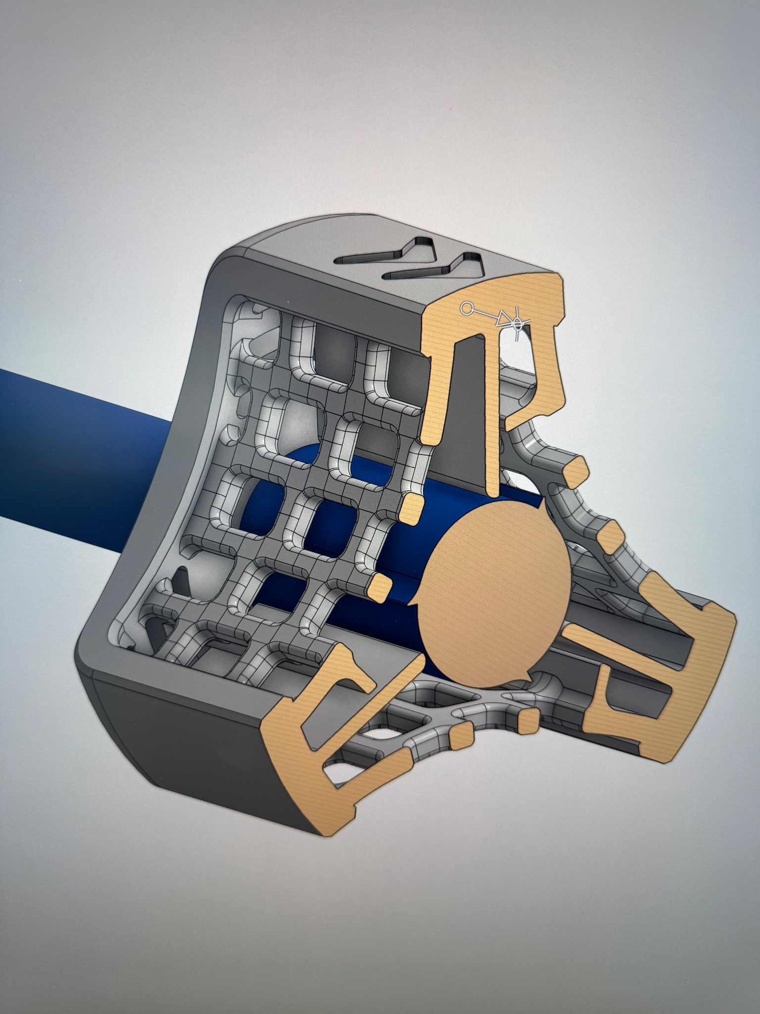
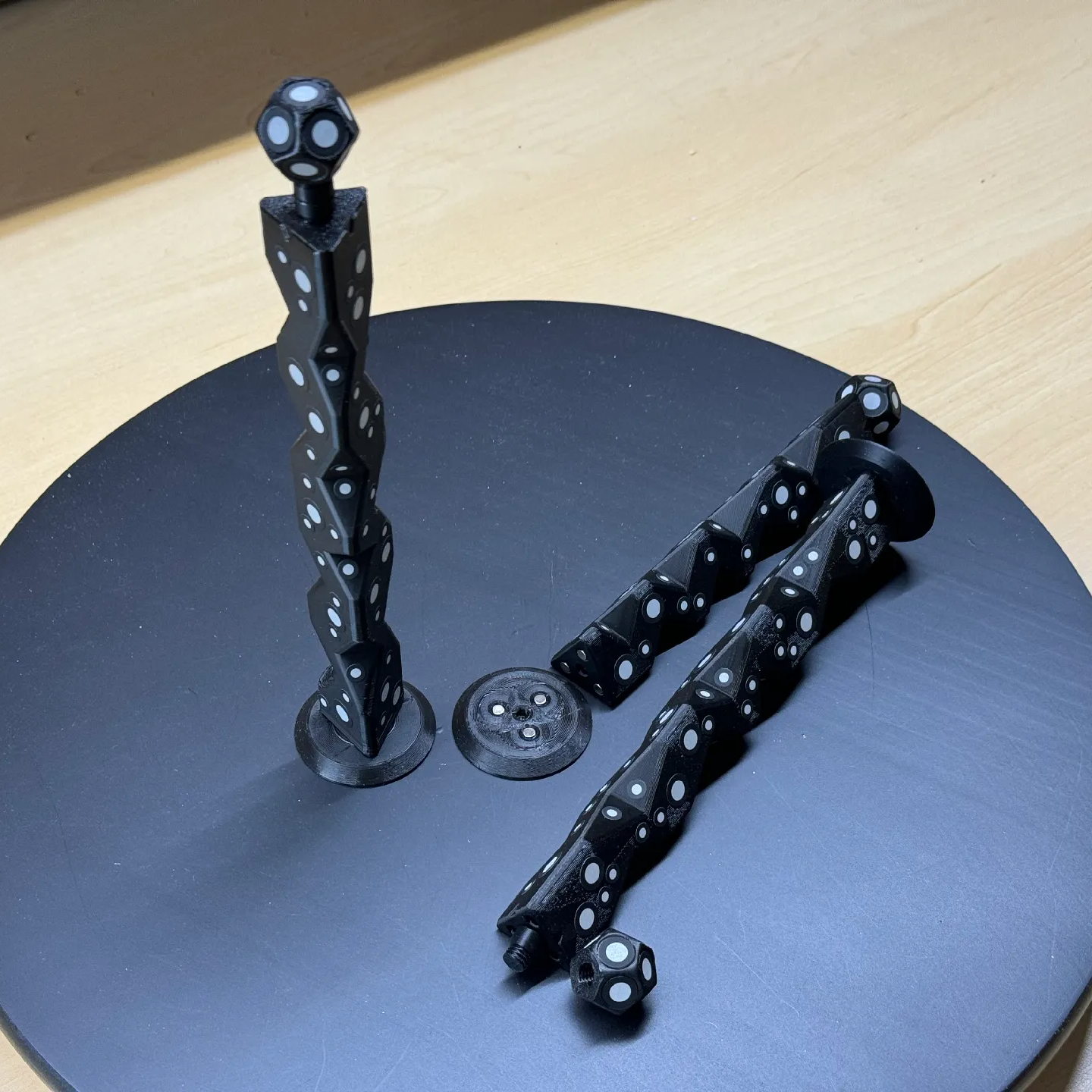
It’s a 3D printed design which can be produced on a Formlabs Fuse 1+ as a single piece in nylon using a selective laser sintering process. The torque wrench works in a deceptively simple manner. As the handle is rotated, a flap mates with the flat side of a fin on the shaft. This allows the shaft to turn. However, apply more than 0.6 Nm of torque, and the fin will eventually give in, snapping over the lip and stopping any further rotation that would over-tighten the fastener. [Sam] suggests these printed torque wrenches largely come out to the correct torque spec when printed, and can survive a thousand cycles or more while remaining in a usable spec.
The wrench does have one drawback though—it is apparently painfully loud to use. When the handle snaps past the detent, the “click” is quite piercing. [Sam] has measured the sound at up to 125 dB. Not exactly the best when it comes to ear safety!
If you work on MRI machines regularly, you already have the tooling to do your job. However, it’s neat to see that such a specialized tool can be easily and reliably 3D printed… with the slight drawback that you need a $60,000 SLS printer to do it. SLS isn’t readily available at the DIY level just yet, but it is slowly getting there. We’re waiting with bated breath.