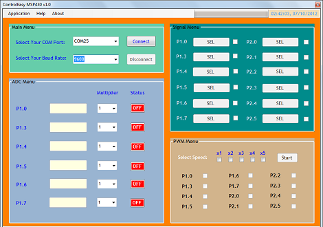
 Sometimes you need to toggle or read a few pins on a microcontroller for a project so simple (or so temporary) that coding some firmware is a rather large investment of time. [Jaspreet] had the same problem – wanting to read values and toggle pins without writing any code – so he came up with a rather clever solution to control an MSP430 through a serial connection.
[Jaspreet] calls his project ControlEasy, and it does exactly as advertised: it provides a software interface to control ADC inputs, PWM outputs, and the state of output pins via a desktop computer. ControlEasy does this with a matching piece of code running on any MSP430 with a hardware UART (like the TI Launchpad) sending and receiving data to the computer.
Right now ControlEasy can read analog values, generate PWM output, and set individual pins high and low. [Jaspreet] plans on expanding his software to allow control of LCDs and I2C and SPI devices.
In the video after the break you can see [Jaspreet] fiddling around with some pins on his LaunchPad via the GUI. The software is also available for download if you’d like to try it out, but unfortunately it’s a Windows-only build at this point.
[youtube=http://www.youtube.com/watch?v=rMAQzwj42QI&w=470]


Anybody done this with a Mega yet?
http://myrobotlab.org/content/new-149-arduino-gui-overhaul has promise.
http://indiantinker.wordpress.com/2012/08/25/arduino-controlware-v-1-0-beta/ but it’s UNO only and needs a few more features to be “production ready”.
I will contact you after completing this GUI.
It can be done with the same GUI. You just need to develop a code for the Mega. I can do it in a hour or two but for that, i have to get one for myself !
A friend of mine has done this for UNO. You can check it out http://indiantinker.wordpress.com/2012/08/25/arduino-controlware-v-1-0-beta/
I would send you a MEGA to keep if you would develop the GUI to control it “manually” like this.
I had done something similar some time back with Arduino. The GUI was written in wxPython. I had it uploaded to one of those free hosting sites which went down. So this become a post in my newly started blog
http://navinbhaskar.blogspot.in/2012/10/arduino-controller.html
Hi,
As I had promised earlier I have made some improvements to the app. Most importantly, I have created the win executable out of python scripts so that you do not have to install python and required libraries. This is not final version, I need to do more improvements. Please send in your valuable feed backs and suggestions that I will try to incorporate them in the final version.
http://navinbhaskar.blogspot.com/2012/10/this-blog-post-is-continuation-of.html
Hi,
I know I am very late on this but I was trying to add telnet support along with the serial interfcae. But my ethernet shield would not work. So I have uploaded the project without telnet stuff. The new version has improved GUI and programming interface. Currently it support Arduino, mega and mbed. I Hope that this helps you .
http://navinbhaskar.blogspot.com/2013/02/arduino-controller-3.html
http://www.ev-power.eu/Measure-Test-Tools-1-1/LAN-controler-with-relay.html?cur=1
This product has basically the same UI. Really helpful and universal piece.
That’s a really neat idea. Is the serial command language documented? If it is, it could be the basis for making the GUI work with many other micros.
https://github.com/areben/ROCKETuC
Library for processing
Demo of GUI
http://www.youtube.com/watch?v=DlkVVfvfR4I
i highly recommend xscada
it can be downloaed here
http://www.micset.net/
its worked well for a few hmi projects i did with microcontrollers
Definitely useful.
I’m working hard on something similar right now for PIC24. The main difference is the GUI on the PC side is mostly defined by the MCU; so you can add or change something without reprogramming the GUI. Or even use a different MCU altogether, and everything is being designed with easy porting in mind.
Hardware devices on the MCU are represented as objects, each with a name and a list of properties. An object can optionally be parented to another object, or a property to another property, allowing the PC to display all available MCU resources in a nicely structured tree; which can be expanded or collapsed to show only what you’re using. You can even connect multiple MCUs, and they’re shown in the same tree.
The MCU keeps track of which object/property definitions, and changed property values, have been sent to the host. This is kept in a bit array. When the host sends a “Scan” command, the MCU scans the array, finds the first update and sends it to the host, then clears the bit. Or send an “Autoscan” command, and the MCU continuously sends all available updates as an idle task. A second bit array acts as a mask, allowing you to turn off updates for any objects/properties you’re not currently interested in; saving processor time and bandwidth.
The property definition includes its name, and whether it can be read/written. Most importantly, it includes typing info, some examples:
1) Numeric, various integer and float sizes, with optional min/max limits.
2) Enumerated value. Essentially a limited numeric, but also returns text descriptions of each valid value in its definition. Like True/False, to allow a boolean property. Or a list of available analog pins.
3) String. Can be read or written in its entirety.
4) Stream. Like a string, but can be partially read, and writes are treated as appends. Usually represents an underlying ring buffer. Useful for things like UARTs, or ADC channels that have been set to sample continuously.
5) Null. Serves only as a node in the GUI’s tree, to which other properties can be parented.
This allows intelligent display and editing of virtually anything in the GUI, with only a limited and fixed set of editors required.
You can also open up an oscilloscope window, and drag any property over to it; allowing any set of properties to be displayed with a common timebase. Even string or stream properties. When they’re read, it shows a tick at the bottom of the window, which can be hovered over to see the value.
There’s more, but this is long enough. ;)
Your idea is great ! The GUI which i developed is just for sending instructions … The rest of the task is dependent on the code inside the uC i.e, the GUI is not uC dependant. After completing this GUI (will require maybe a week or two), i will shift to other TI platforms C2000 & Stellaris launchpad and will develop algorithms to control them using the same GUI.
I made something similar to this on an Arduino Mega board for a customer a while back but they never used or bought it. I used BertOS though and not that horrid Arduino IDE ‘thing’. I should do some more work on it methinks and publish it.
You should – surprised that something like this isn’t available on a widespread basis yet.
I stumbled upon this:
http://waterbearlang.com
Could be interesting
Typical engineer’s GUI: Fucking ugly. Are you colourblind?
I will keep this in mind while designing the rest of the interface :)
Mod +1 for tastefully handled.
I cannot get the GUI to run, code is on the Lanuchpad, 2553 chip, but GUI tries to load for 1/2 second, then no dice. using XP pro, 2gb ram, CCS5. 5.2.0.00069 and TI Launchpad 1.5
Have you selected the correct Virual COMM Port? To check which COMM Port to connect to, Right Click on My Computer select Properties.. .go to device manager and Check PORTS (COM & LPT) … You will find something written like this “MSP430 Application UART (COMXX)”. Also, make sure that the baud rate is set to 9600.
Also, make sure to connect the RXD & TXD jumpers on the MSP430 in H/W UART mode. (The small leaflet or the quick start guide that comes with MSP430 shows how to do this).
I have the same problem, but Win7 64bit. GUI just doesn’t load. Run the executable and it’s like nothing happens. I’ve tried to run it as admin as well. Unfortunately it looks like the only way to get support is to e-mail him directly.
I am using the Win7 64bit version and the GUI is working perfectly fine ! Try installing this: http://www.microsoft.com/en-us/download/confirmation.aspx?id=27757
Note: You require .NET framework 4.0 to successfully run this app.
Still not able to run this. Anything else required? It just doesn’t do anything when I run it.
For MSP430 why not use the GRACE GUI for CCS? It’s really cool and SO easy to use…
http://processors.wiki.ti.com/index.php/Grace_Quick_Start_Guide?DCMP=Grace&HQS=Other+OT+grace#Welcome
…just sayin’
:)_
Forgot to mention… you can use it stand-alone as well!