The word hacking got its start with model railway clubs, and the state of the art belies the current advancements in computer control and very, very small microcontrollers. [Jim] put together a great tutorial for driving model locomotives with a microcontroller, in this case an ARM-powered mbed.
Low-end model locomotives are controlled with DC, so an H-bridge and a PWM out on the mbed makes sense to drive these trains. [Jim] wired up a Pololu H-bridge driver, connected it to his mbed, and everything ran great.
Rail switches are another matter entirely. These allow trains to move from one track to another, but having them go to the left or right requires powering a fairly high current solenoid with 15 to 24 volts. For this, [Jim] used a MOSFET power control board to switch the rails and came up with a pretty neat demo that shows a small locomotive going back and forth over a single rail switch.
There is another class of model locomotive – ones with Digital Command Control. This setup is just a small decoder chip that fits inside an engine and tells the locomotive to turn on a lamp or run a motor digitally, allowing the conductor to control multiple trains on the same track.
[Jim] goes through the basics of DCC using the mbed, allowing two trains to switch positions in a rail yard using computer control. It’s really cool stuff that leaves us wanting a little more room in the basement to start building a huge computer controlled model railway.
[youtube=http://www.youtube.com/watch?v=X6oJ_3nrTJ0&w=580]
[youtube=http://www.youtube.com/watch?v=CMA0reXSTiM&w=580]
[youtube=http://www.youtube.com/watch?v=2MC5PbsC9eE&w=580]


This is Awesome!
As a geek and a model train nut, I’m thrilled to see this kind of story on hackaday!!! Granted, I tend towards traditionalism when it comes to model trains (o gauge, specifically postwar Lionel), but any model train related hack can be applied to any of the hobby scales quite easily! Very cool! (Heck, I might just watch these videos…)
I enjoy my share of O scale as well, as you got me thinking of seeing what I can do to put a micro in it, thanks!!
This reminds me of my university course where we program model trains (https://www.student.cs.uwaterloo.ca/~cs452/) — This post has me really wanting to get my own setup again!
Makes me want to take my HO or N scale out of the box and see what I can do with what I know now and microcontrollers or even a RPi!
The main difficulty I have found to be positional awareness. To fully automate train movements you will need to know exactly where each train is. Which is a very difficult thing to do using basic sensors..
A video camera placed above the track and some software might work.
Interesting – I’ve been working on a signalling system for a much larger setup, and locomotive detection is proving to be the major bug bear.
We’ve been trying to keep the cost of the detectors down, so, in order, thus far we’ve tried: microswitches and drag plates, magnets and reed switches and now force sensitive resistors under the track (we have mass on our side, at least!), but who knows what we’ll end up with.
Unfortunately the signals aren’t deployed for this video, but here’s me doing a run on our track (steaming bay to steaming bay): https://www.youtube.com/watch?v=SsS4CwX8s2o and here’s one of the lamp driver boards all wired up and in testing: https://www.youtube.com/watch?v=AUvppr_nHGQ complete with high-speed typing as I enter hex numbers to a terminal to test the protocol :D
IR transmittor and receivers might work? There are cheap 38khz receivers: TSOP4838, they cost about 1.50 euro. IR transmittor with unique codes in the train bottom.
No moving parts, pretty cheap to make, easy to interface.
Would it not be possible to use light sensitive resistors? Of course this would not work in a dark room, but in a well lit room you should be able to detect the difference between track open and something on the track.
Alternatively you could get IR sensitive diodes (not the 38khz ones, since you don’t need to transmit any data), and outfit the engine with an IR LED pointing at the track.
How about acoustic triangulation of the train’s whistle? Maybe the unique sound of each train’s whistle could be used to identify the train too?
Camera won’t tell you if a train is hiding in a tunnel!
IR sensors mean you have to pull up all of your track! :-(
Why not? I see no reason the IR option fails in tunnels. If you’re relying on an IR emitter mounted above the layout, you may need to add one (or more) to tunnel ceilings, but that’s easy enough.
I don’t think anyone said the IR approach wouldn’t work in tunnels. A video camera mounted above the track would have a hard time tracking the location of trains in the tunnels though.
The approach of attaching the IR transmitter on the bottom of the train would probably require the IR sensors to be mounted under the track where it’s mounted to the substrate. That seems like a task to be avoided on most train layouts I’ve seen.
I did a pretty decent job with nothing but microswitches that detected when trains drove past for locomotives only: It gets way harder once you have a whole train that you won’t have calibrated data for. Since the same controller knew exactly when it sent speed commands and controlled turnouts, dead reckoning got us within +- 5mm by the time it hit the next sensor (placed at fixed locations, especially near turnouts) which would only get better with time.
It was a lot of work, though. I have a few ideas for better (cheap!) sensors, so I’ll be sure to make a HaD post when I get things working.
How about sensing track current? I don’t know how long the powered segments are in a typical layout, but you could separate the rail handling return current at whatever interval is useful without changing your power wiring. Return current sensing is simpler to measure than high-side current anyway.
Current sensing is used in a bunch of layouts (Like MIT’s TMRC), but it has the downside of only detecting powered locomotives: If you’ve got a metre long model train, you really do want to know where the whole train is, not just the motive power.
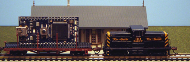
That’s actually a giant scale model on a full size flatcar…
@mikemac. Oops you’re right. I misread that.
I’m a longtime member at the Tech Model Railroad Club (TMRC) at MIT, so I think I can offer a few practical comments. We locate the trains via conductivity in electrically isolated blocks, where the blocks vary in length from 2 to 15 feet, depending on circumstances. Locomotives are easy, but we can sense any car too, because on each one, there’s an axle with a 39K resistor across the wheels, a surface mount component bonded with conductive epoxy. So we can’t tell exactly where a train is in a block, but we can tell which blocks have locos or cars in them, and we do use the information to run signals, though we need to build a lot more of them. Sensing actually is on the high side, with a 0.1mA bleed current applied to the track, and then an A/D converter reading the voltage on the rails. If there’s nothing there, the voltage is above the A/D range and the reading is 0xFF, if there’s a loco there it’s some very low value, and if it’s one or more cars it’s somewhere in between. This works because every block is wired with a diode in series, so it can source current but not sink it–without this feature, setting a zero voltage on the track would prevent you from sensing whether the block is occupied. We’ve used this scheme since the 1950s, when the sensing was done with relays. We do try to keep up the tradition of building good hacks!
I hadn’t thought of putting a resistor across the wheels like that! Is there any particular reason it was 39k? Got any pictures?
I’m considering adding very small sections to my next layout to detect single axles through this technique now. It seems much nicer than trying to use microswitches or infrared detectors.
I’m really jealous of TMRC; I’m not really aware of anything else like it in the world. It’s enough that I
Oh, TMRC is unique!
Since you asked, I’ve put a picture of a resistor installation on our website (and I see that they’re 38K not 39K!) Go to http://tmrc.mit.edu/ and click on Progress.
The selection of 38K was a typical engineering compromise. We want something that will give us a useful reading on the A/D converter for a single car, but which won’t draw much power if there’s a whole string of cars in a block. And we’ve learned that you don’t want to make the resistance too high, as the rails aren’t perfectly insulated, especially if there’s scenery work going on which might make the area damp. The result of that could be a false occupancy, so we use a resistance that’s “high enough” but also “low enough”.