Controlling A Railroad With An Mbed

rr

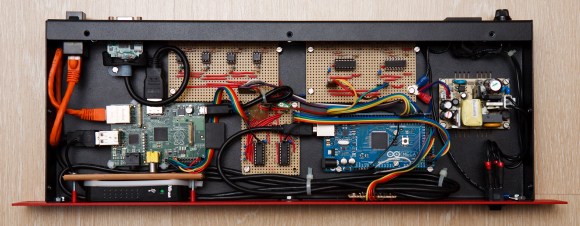
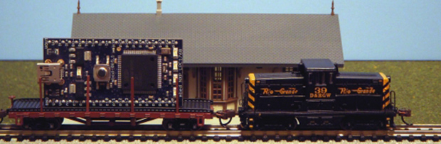
The word hacking got its start with model railway clubs, and the state of the art belies the current advancements in computer control and very, very small microcontrollers. [Jim] put together a great tutorial for driving model locomotives with a microcontroller, in this case an ARM-powered mbed.

Low-end model locomotives are controlled with DC, so an H-bridge and a PWM out on the mbed makes sense to drive these trains. [Jim] wired up a Pololu H-bridge driver, connected it to his mbed, and everything ran great.

Rail switches are another matter entirely. These allow trains to move from one track to another, but having them go to the left or right requires powering a fairly high current solenoid with 15 to 24 volts. For this, [Jim] used a MOSFET power control board to switch the rails and came up with a pretty neat demo that shows a small locomotive going back and forth over a single rail switch.

There is another class of model locomotive – ones with Digital Command Control. This setup is just a small decoder chip that fits inside an engine and tells the locomotive to turn on a lamp or run a motor digitally, allowing the conductor to control multiple trains on the same track.

[Jim] goes through the basics of DCC using the mbed, allowing two trains to switch positions in a rail yard using computer control. It’s really cool stuff that leaves us wanting a little more room in the basement to start building a huge computer controlled model railway.

Continue reading “Controlling A Railroad With An Mbed”

The RPC: A Stand-alone MIDI Workstation

raspiMidiRPC

Not just another pretty enclosure, this shiny little red box is [Lauri’s] stand-alone MIDI workstation. The build uses an Arduino Mega 2560 to handle the MIDI inputs and outputs. It communicates via serial with a Raspberry Pi that acts as a sequencer and oversees all user interactions. The Pi’s SD card offers convenient storage for your work, though we wish it was easily ejectable from the front of the box and not trapped under the hood. [Lauri’s] RPC also squeezes in the necessary USB hub for the RasPi and an HDMI-to-VGA converter. As an all-in-one solution, this is a sleek little box that–once paired with some software for arpeggiators, chord harmonies, and scales–will be a handy MIDI sequencer with robust control ready to be conveniently mounted on your rack.

Now all you’ll need is something to plug in. Why not check out the custom MIDI recorder we featured last week, or the organ-to-MIDI keyboard conversion for inspiration.

[Thanks Teemu]

3D Printering: Where Can I Get The Cheapest Filament?

printering

We’ve complained about the price of 3D printing filament, and cheered at the machine that makes filament out of plastic pellets. Still, the price of filament for our 3D printers is climbing ever higher, leaving us to wonder, where can I get the cheapest filament?

Now, I’m going to start this of by saying this is a work in progress. Canvassing suppliers on every continent for 1.75 and 3mm ABS and PLA for every possible color while accounting for different amounts of filament and shipping is a whole lot of work. Therefore, we’re going to do this in parts, first starting with how much it will cost me to get a kilogram of PLA shipped to my door. This should be a valid test for just about everyone in the USA.

The test criteria is simple: find a supplier of PLA on the Reprap wiki printing material suppliers page and figure out how much it would cost me to get 1 kg of white or natural PLA shipped to my front door. I’ve organized this in a spreadsheet (below) that contains the supplier, size (1.75 mm or 3mm), weight (usually 1 kg although some suppliers are about three ounces short), color, and price with shipping included.

Continue reading “3D Printering: Where Can I Get The Cheapest Filament?”

Reactive Target Range For Nerf, Airsoft, Etc.

reactive-target-range

Taking the time to build a reactive target range really adds to the fun of toy weapons. It lets you move beyond just point and shoot to actual games of skill.

The project is anchored by an Arduino board. It connects to a piezo element on the back of each of these sheet metal targets. Detecting when a projectile hits the target works pretty much the exact same way the ever popular Knock-block works. To provide interactive enjoyment each target has an LED which, when lit, indicates that the target is active. From here it’s just a matter of coding to add different challenges. So far [Viktor Criterion] has implemented quick draw, timed, and rapid fire modes. The demo after the break shows off everything, including the slick modular design he came up with to make the system portable.

We’d love to see these targets mounted on motorized tracks. Each round would have the targets moving closer to you at a faster pace to keep you on your toes.

Continue reading “Reactive Target Range For Nerf, Airsoft, Etc.”

Unreadable Binary Epoch Clock Is Unreadable

binary-epoch-clock

What time is it? For that matter, what is the date? This clock can tell you both of those things, if only you could read it. The inspiration for this Binary Epoch kit came after a friend of [Maniaclal Labs] built an eight-bit binary clock. That’s a pretty common project that gets riffed on for things like mains-timed logic-driven clocks. They figured why not make it bigger? But even then you can make some sense out of the display after studying it for just a bit, you won’t be much closer to answering those two questions.

The problem is that this is unreadable in a couple of different ways. First off, how long did it take you to figure out in your head the decimal equivalent of the binary number displayed above? We gave up. But pounding the number into Google (search for: 0b01010010000010000001001010010011 in decimal) gives us 1376260755. meaningful? Again, not to a human. This is Unix time, which is the number of seconds elapsed since the Epoch: 8/11/13-22:39:15.

Check out the video below that shows how to set the clock, which uses a menu system for human-friendly input. But since it’s Arduino compatible you can also connect an FTDI cable and program it from a computer. Oh, and since this is Open Source Hardware (note the icon in the lower right) you can get all the info to build (or breadboard) your own from their Github repo.

Here’s another complicated clock that uses Nixie tubes to display time and date info which is actually of use.

Continue reading “Unreadable Binary Epoch Clock Is Unreadable”

Making The Electronics For A Doppler Motion Sensor

There are many different sensors that can be used to detect motion in a given environment. Passive InfraRed (PIR) sensors are the most used today, as they work by detecting moving heat signatures. However, they are less reliable in the hotter days and obviously only work for animals and humans.

Sensors like the one shown in the above picture started to appear on the internet, they use the doppler effect to detect motion. I (limpkin) designed the electronics you need to add in order to get them to work.

Here is a simple explanation of the doppler effect: if you send an RF signal at a given frequency to a moving target, the reflected signal’s frequency will be shifted. It is commonly heard when a vehicle sounding a siren or horn approaches, passes, and recedes from an observer. The received frequency is higher (compared to the emitted frequency) during the approach, it is identical at the instant of passing by, and it is lower during the recession. Continue reading “Making The Electronics For A Doppler Motion Sensor”

Playing With An Oscilloscope You’ll (probably) Never Own

We’ll have to admit that we were really jealous when [Shahriar] sent us a video he made, in which he casually explains how a $500,000 160GS/s 62GHz oscilloscope works and then starts playing with it.

Even though you need to be quite familiar with electronics to fully understand the oscilloscope’s inner workings, [Shahriar]’s step by step explanation is still approachable for those who only understand the basics.

In the first half of the video he uses the manufacturer’s documentation which contains the oscilloscope block diagrams, so you’ll also learn about:

  • timer interleaved Analog to Digital Converters (ADCs), which allows you to increase your input sampling rate by using several of them
  • phase-locked loops, which use a reference clock to generate a much faster clock signal
  • custom made dies and the materials used for high frequency electronic components

In the second half of the video [Shahriar] connects a pseudo random binary sequence generator and uses the oscilloscope to make several measurements that you’d typically want to know for high speed signals (jitters, eye quality factor…). He later performs a small experiment where he up-converts the frequency components of two random 3.12Gbit/s signals and tries to recall each original signal using the oscilloscope functions, making this part of the video a bit harder to keep up with.