Despite how useful multimeters are, there are a lot of limitations you just don’t think about because they’re the way electronic measurement has always been done. Want to measure voltage and current simultaneously? Better get two meters. Measuring something in a dangerous, inaccessible, or mobile place? You could rig up a camera system to show the meter’s display on a monitor, you know.
Mooshimeter is the better way of doing things. It’s a multichannel multimeter that communicates with your cell phone over a Bluetooth connection. With two channels. the Mooshimeter makes it easy to graph voltage against current to plot a beautiful IV curve on your smart phone. Being a wireless multimeter means you can stick the Mooshi inside a robot and get instantaneous feedback of how hard you’re driving your motors.
Far from being a two-trick pony, the Mooshimeter is actually a pretty good multimeter by itself. It can handle 600V and 10A with 24 bits of resolution. Here are the complete specs. The Mooshimeter is available for preorder here for $100 USD.


yes, yes, it’s ein Muschimeter
Now what are you gonna measure with that?
Well….google muschi why don’t you? :P
The group behind this is Mooshim Engineering… which is QUITE different than the German slang word for a woman’s vulva or also the Romanian word for “muscle”. Grow up, please.
Where’s the fun in that? Growing up sounds lame.
I like how the ad video (0:25) says that the Mooshimeter can go “anywhere”. Certainly has a well fitting shape.
My thoughts exactly :D You’d think they’d research a name before marketing a product, but no.
Interesting. Smartphones really make nice ready made UI for many projects. Does this use bluetooth 4.0 ?
says bluetooth low energy in the FAQ so yeah
Often it’s the UI that increases the size and price of a device. Even if it only requires a few buttons and knobs. The laptops, tablets and smartphone have a high-resolution colored screens, touch-screen and/or buttons. Why not take advantage of these? This applies to tools, toys and gadgets.
I already own a Saleae Logic and I’ve been waiting for a multimeter solution. It’s finally here! ;)
For most interesting things it isn’t the interface _hardware_ that costs money. (which is the “only” advantage using a smartphone brings). There still have to be UI development where the limited and combined output and input surface can cause problems in themselves – the lack of physical feedback like from a selector switch is one example. Effectively communicating with the device can also cause problems some of which are artificial ones (mostly created by Apple for their platform).
On the other side data logging and processing is much easier on a smartphone than in an embedded controller.
The problems you mention are up to the phone manufacturer, mostly, to fix. The app writer for the interface just uses the tools he’s given.
I could see a use for a little tablet just for controlling like this, with Bluetooth and a touch-display. Since tablets and phones exist so cheaply, there’s probably no demand for a stand-alone solution. Maybe in the near future Bluetooth will be a popular thing for instruments, with very little real display of their own. Makes sense, since displays are expensive except in the vast quantities tablet / phone makers use.
Bluetooth offers PC connection built-in, as well as the ad-hoc use of the engineer’s mobile phone. For a permanent display, just build an Android tablet into the casing, same way Windows CE is used now (except better, of course!).
As well as a virtual display / control set, some standard software could be written, allowing lots of kinds of analysis to be done, with any instrument following the Bluetooth Scientific Data standard, which I have just invented.
I wonder if anyone makes an IEEE488 adaptor for Bluetooth?
Just thinking more, but for things like radio work, where 2,4GHz transmitters would interfere with the measurements, you could perhaps have a fibre-optic version. Infra-redtooth.
[crawls back to his bunker]
May be Bluetooth Serial + Serial IEEE488 adapter? Not going to be fast.
There are a few DIY IEEE488 projects on the net, so that might be a starting point.
I was kindof joking, surely nobody still uses IEEE488? Since that’s partly what this would be replacing. Maybe they do, it just seemed like something clunky and outdated in the 1980s.
Best thing is that there are free and fairly easy to use tools that allow you to create android apps. Google MIT’s appinventor – contrary to what you might think you can create some fairly advanced apps with it
Here have a look
https://www.youtube.com/watch?v=5Pt3Jqx99pw (not reall microcontroller related – created this because I saw a similar hack based on raspberry PI here on hackaday)
or
http://www.youtube.com/watch?v=cSDkNptPpYU
I’ve made a bunch of projects that use bluetooth to interface with microcontrollers. Usually it’s a lot quicker and faster to just write an app than to wire a TFT LCD screen and add buttons to your project.
Do you want to know what “Mooshi” sounds like in German?
Dit not pick up on that… maybe my mind is not as dirty as yours…
zis feels so natural to use zith the ipad!
Does it have “beep” build in?
Okay guys, I’m no getting these MOOlti-pass, MOOshi-meter puns…
!no s/not/
these are two very different project from two very different persons ;)
projects*
The long form name of the mooltipass is, “Leeloo Dallas Mooltipass”
cool. I bet the bluetooth is most of the cost, I think iphones are still ~$600, which I suppose technically makes this a $700 meter… :-) Nice its 2 channels, thats always bothered me about standard meters, and still, do ANY meters even TRY to do watts?
has android support too. With 2 channels its plausible that they could do a watt output graph.
Only the newest generation of Android devices have Bluetooth LE. Neither my phone nor my brand new tablet have it.
Android 4.3 was first for BLE. My phone is still on 4.1 :/ No community rom support for it either god damnit.
Let alone the fact I dont have the hardware support of course
ipod touch is $229 new
can probably do better used
what was that price again?
It’s the straw man price. Because nobody on the planet is going to buy an iphone just to use with the meter and nothing else.
I find older iPhones at the junk yard all the time. Really not an issue. Also, you can use their API which means you can connect to any other bt device (apparently).
The BT LE profile is only available in iPhone 4S+ and 5th+ gen iPod: http://en.wikipedia.org/wiki/Bluetooth_low_energy#Hardware
Android 4.3+ should support it (depending on the particular device’s radio)
Well yes cost is still an issue; many, and I would go as far to say as most people don’t live near where serviceable technology is casually tossed away so it can be had inexpensively.
The obvious assumption is that you already have the phone… and you can get cheap wifi-only Android tablets for $50. On the hardware side, BLE is cheap. BlueRadios sells their BLE modules for a shade under $9/ea in quantity.
I’ve never owned a cell phone in my life.
cool story bro
As far as meters trying to do watts, I’m aware of three. The Gossen Metrahit Energy is a pricey professional solution that will measure current and voltage simultaneously, DC or AC, any waveform, well enough to do various power calculations. It’s not cheap. The P3 “Kill a Watt” does a similar job, but only for mains power of approximately 120V, 60Hz, 15 or less amps. It’s relatively affordable, great for measuring the power consumption of home appliances. The “Watts Up” meter does a similar job for DC applications only, great for measuring battery powered circuits. All three of these meters will also measure cumulative energy, as well as power (energy being the integral of power over time).
There aren’t many meters that measure watts. I’ve usually seen it done by using two separate meters for DC applications, or two probes of an oscilloscope for AC applications (combined with some math functions, multiplying v*a and summing over a full waveform cycle). I’d say there’s a niche to be filled here.
What about this meter?
http://www.aerodynes.fr/2013/09/08/fried-circuits-tester-multiscreen-and-energy-measurement/
There is also a bottom base to connect it to other non USB devices.
It says it has 24b of precision, but it also has 0.5% DC and 1% AC accuracy. These don’t mesh. Perhaps it has 24b of range, but not 24b of precision.
Technically it can be true – precision and accuracy are two very, very different quantities. One is effectively the number of digits you can display, and the other is how close you are to the actual value you’re measuring.
In a practical view, you’re right that there’s a problem with the description.
There is no problem with the description, it is accurate and clear. If you don’t know the difference between precision and accuracy, it is not the job of the specifications to educate you.
If you were trying to be a condescending twat, you succeeded.
If I had a carbon resistor and said it was 1011.2345667738943434 ohms, plus or minus three percent, you’d be OK with that because accuracy and precision are two very different things. Got it.
That would be quite the swing (+/- 303.37 ohms), but thank goodness you at least have the precision to solidify the uncertainty!!!
@ Rob,
that would be +/-30.337 ohms. You were off by an order of magnitude on your percentage calculation.
Accuracy doesn’t mean the precision below n% is “wasted”, rather it means that the calibration or stability of the measuring device over e.g. varying temperatures is guaranteed to within a certain range. You can still make relative measurements with precision – you’re just not so sure about the absolute value you’re getting.
In other words, if you measure a 1011.12 Ohm resistor and a 1011.90 Ohm resistor, the two figures are comparable to within your measurement precision even though both measurements may be 3% off, because they’re both 3% off the same way since the meter doesn’t change between the measurements. If you had used two different meters or the same meter at two different times and places to measure them without correlating the meter readings, then you’d lose precision with accuracy.
That’s called systematic error, an is taught in high school physics when they tell you about how to measure stuff and carry the error into your results.
You couldn’t really meaningfully say that. Any digits beyond the accurately measurable ones are meaningless. You’d be daft to write them down or give them to someone.
Is that the different between accuracy and precision? Cos that’s just false precision. Which really isn’t precision at all.
I haven’t seen my ho, Fluke or Beckman DMM manuals stated it very
differently either. On the other hand, they at least have the decency to
match the accuracy to their resolution.
You are essentially buying an DMM without even a complementary factory
calibration for this $100 price.
ooops. hp DMM. :P
The site mentions they’re going to sort out factory calibration. Or you could do it yourself if you had the equipment (really good 2V voltage source usually).
Site mentions, right at the top
“The accuracies and tolerances listed here are preliminary and conservative. They do not include temperature compensation or factory calibration.”
It’s only a prototype so far, or perhaps an alpha test. You don’t have to buy it yet, and indeed, you can’t.
You’ll need more than just a 2V source unless they are using very good
laser trimmed resistor voltage divider networks with multiple tabs for
the different ranges. You would also need a calibrated current source.
There is no Kelvin (4-wire) resistance measurement for resistance
measurement, so that limits low range accuracy.
BTW when I talk about calibration I mean calibration with traceable to a
standard.
That accuracy is on par with a sub $20 DMM, but not a $100 one. Seems
like such a waste to have so many digits after the decimal points that
are not to be taken seriously. BTW the extra digits even on a good DMM
jumps up/down, so there is a upper limit on how many digits you can use.
You would have thought that measuring frequency better than 1% is one of
the things that even a $1.5 AVR chip can do with a regular crystal.
It *could* be calibrated in theory and ultimately to the tempco and
stability of the components. After all, software can correct the readings
and even tell you the error ranges once you know the offset and gain.
Unfortunately most people don’t have the suitable standards to calibrate
it nor it seems that the people making it has that in mind.
” BTW the extra digits even on a good DMM
jumps up/down, so there is a upper limit on how many digits you can use.”
That depends on your integration time and how much noise you’re getting. With long integration times, you can get down to arbitrary precision – the only problem is that you get a time average of the signal that won’t tell you much about what’s really happnening, so it’s only useful for measuring very precise DC levels for something like biasing an amplifier or measuring a precision resistor.
Where do you get your $100 DMMs? I find that $100 DMMs have 1% / 0.5% accuracy at best. (% varies by parameter – 0.5% DC, 1% AC typically). To get much better you’re looking at $300 or so. This looks like 2 meters for the price of one to me (though lacking in some features I’d expect of even a cheap meter).
Range is the upper and lower bounds of the measurement capabilities. My arduino has a range of 0 to 5 volts and has 8 bits of precision, If I swapped the chip out, I could get 2, 4, 12,16, or even 24 bit precision and yet still maintain the 0-5v range. The provided details do “mesh” even if the terminology is confusing. This is what homework is for.
Just to recap:
Precision = number of significant figures or decimal places, AKA resolution
Accuracy = how close you can get to the median value in a dataset
Range = difference between min and max, usually starting at 0
Slight disagreement:
Resolution describes a device’s output. It’s the smallest measurement you can take from the instrument repeatably. A DRO with 4 digits past the decimal point has finer resolution than a DRO with 2 digits past the decimal, which has finer resolution than an analog needle whose scale is divided into tenths.
Precision describes how tightly the readings you take cluster together. Let’s say we measure the same reference value ten times with each of the three instruments above and take the standard deviations of the three sequences. If the 4-digit DRO’s standard deviation is 0.5 and the analog needle’s standard deviation is 0.025, the analog needle is more precise than the DRO.
Accuracy describes how well the limiting mean value of a series of measurements from an instrument will match the established value of a reference standard. Assume that in the example above we measured a standards-grade 10v Johnson cell, the average of the 4-digit DRO’s readings came out as 9.995v, and the average of the analog needle’s readings came out as 9.97v. The DRO is arguably more accurate than the analog needle, in spite of having less precision.
Conclusions:
– Resolution beyond a device’s precision is a waste of space. 3.141592653589793 (footnote: +/-5%) is pure marketing wank.
– You can get good measurements from a device with good precision and a good calibration history even if the device isn’t particularly accurate. The measurements you take will contain an error, but the calibration history allows you to quantify that error.
– An accurate device will give you better values than a precise one over the long run, but you have to compare the relative accuracies and relative precisions to decide how many measurements you need to take before you can trust the accurate one more than the precise one.
– A calibrated, precise instrument allows you to have the most confidence in the accuracy of a single reading.
Whyyyyyy just when i think of something and too lazy to bring that idea to life,somebody makes it :D xD **next thing on my mind will probably be a laser gun star wars thing
lame
Is that your way of making a wish? “Next thing somebody’ll dump a big bag of money on my doorstep, t’sk!”
I’ll wait for dave’s tear down on EEVlog
Thanks to Dave’s informative teardowns & demos, I’ve been eyeing up buying the same(-ish) bluetooth Agilent multimeter that he often uses, which is very similar (in basic function) to this box. While I don’t have a specific use-case, I like the idea of having data-logging & remote viewing on a cheapish tablet (i.e. N7).
I think I’ll just stick to regular multimeters.
This IS a regular multimeter, with a remote display.
Not to me it isn’t.
less the display, and probably the precision and safety. thankfully it is far away from the user.
So this is just an ad? No schematics – just a link to buy?
they don’t come to your house and give you personalized instruction either
Well, it leaves a lot of questions open, like how are the current/voltage measurement channels isolated from each other, or can you cause an accidental short, or a high voltage leak by measuring one thing with one and another thing with the other.
Seems to me for starters, that both channels share the same ground because there’s only one hole for it.
Obviosuly they’re not isolated – when measuring V/I on a single supply they’d rarely need to be. If you want isolated, just buy 2 of them!
Would be nice to have an efficiency display mode with 2 units measuriong input and output of a PSU or DC/DC converter
that’s a software project
I love that idea!
One of the things I’ve been wrestling with is how to provide a good multi-mooshimeter experience on such a small screen. Specific use cases like these are great.
Well obviously they should be isolated if you’re intending to be measuring two things at the same time, because you’re not always measuring the current and voltage of a single component. That’d be rather pointless because usually you only need to know one thing, like the voltage of a capacitor, or current through a resistor, and you know the other automatically.
You often need to stick your leads in two places because you’re interested in e.g. battery voltage and amplifier output current, which means you have to stick your ground lead to the battery ground and the output stage, tying the two together and causing noise and stray currents to travel from one to the other through your meter.
Actually buying 2 is a good idea, if you had a complicated project, you could connect a few of these all over the place, and inside things. Could maybe be a bit cheaper, depending on who you are and what your projects were. But you can’t do much better for isolation between channels than completely separate sensors.
iPhone only? I thought nerds preferred Android….
From the FAQ:
“From Apple, we support iOS 6 and 7 devices that are Bluetooth Low Energy enabled. Currently, this includes iPhone 4S and later, iPad 3, iPod Touch 5, and iPad Mini.
For Android we support 4.3 and later with native BLE support.
We will offer limited support for desktop linux at launch – API only.
We do not intend to support BlackBerry or Windows Phone at launch.”
Shame there isn’t a fallback Bluetooth 2.0 (or 2.1) mode. But AIUI the two Bluetooth standards, BLE and normal, are completely unrelated except in name, so he’d need to implement both separately.
I wonder if they make BLE 2.0 adaptors?
http://www.seeedstudio.com/depot/bluetooth-multimeter-p-1535.html
No not wide range and multiple, but significantly cheaper.
And more to the point – fully open sourced…
It doesnt use standard probe connectors so taking measurements on circuit traces, large cables, would be difficult, unless you want to solder some 1/8″ headphone jacks to probe extension cables. Also the maximum voltage is only 30V and max current is only 1A with 3% precision.
Well it isn’t ideal but at least it’s reasonably priced and open source. Sure it could be improved
hopefully, because that one is limited to <30V, hardly the kind of scenario you need a remote display…
The plastic shield around the voltage connector is a nice touch, just like my ancient fluke DVM.
Bluetooth is just what the doctor ordered for electrical isolation. Make sure the fuse is easily replaceable! I used to blow the fuse on my fluke all the time, testing the current draw of my appliances.
Would it pass UL? It looks good!
How would this isolate you from a circuit anymore than a normal battery powered DMM.
If I wanted to hook a normal battery powered DMM up to my computer, I would have to worry about ground loops, isolation, cable length, etc.
Battery powered DMMs dont use optoisolators? I would imagine they do for this very reason.
If you want an isolated PC connection (or logging at all), add $50 – $100 to the base DMM price, generally.
Mine has:
http://www.thebits.info/general/n56fu-172.htm/comment-page-1
tl;dr, cheap chinese multimeter with rs-232 to IrDA to USB for optoisolation.
Had me interested until I read the pricetag.
100$, ouch…
I’ll be patiently waiting for a more sensibly priced version.
In the spirit of HAD, it will be more fun to hack one together!
I have a few remote reading fluke meters at work, they can be used a regular meter, which is nice as everything is always together and when I need to do a floating reading at high voltage, I just pop the display off. They can’t do dual readings at the same time without using more than one of them and the battery life isn’t all that great. An improvement with this mooshie meter I guess, but not really a “new” idea at all. The extra measurments you can do is where this shines.
I like the plastic blast shields, but don’t see any isolation slots cut in the board. Will wait for Dave Jones to not turn it on, but take it apart.
if you dig around the Website you will find a picture of the 5 Prototype boards and the last board (current one) does indeed have the Isolation slots, if you look at the image with the plastic shields these are actually in the PCB slots.
Had to order one this is so useful (esp for testing vehicles)
The “isolation” in this case is how much the plastic case has when you are holding it and how much the air gap you have when you are running it remotely via bluetooth. :)
That may be good protection against shock, but that’s not enough to prevent arc blast. When dealing with high voltage, high current supplies, you don’t want to let a spark go from one probe to another, even if it all stays contained inside the meter. Because once the spark happens, there’s going to be a huge arc and boom, and that little plastic case won’t contain it.
To be fair, arc blast isn’t a serious concern for most people who don’t deal with high energy power distribution, and most such people aren’t going to be using any crowd-funded meter.
There are 2 PCB cut outs along that voltage terminal. First picture on their website slide show is the internal PCB. http://moosh.im/
Internal PCB also show on their pre-sale site.
http://www.dragoninnovation.com/projects/34-mooshimeter
Not sure if they would get UL etc type of safety certifications.
The “blast shields” slide through the PCB. You can see the PCB on the site.
Won’t you run into Heisenberg uncertainty when measuring current _and_ voltage simultaneously?
you might, or you might not… but as soon as you check it’s all screwed up. best to leave it alone…
24 bits of resolution! O_o Am I out of touch or does that sound absolutely huge for a multimeter?
24 bits resolution is what you get from a $5 sigma-delta ADC these days. It doesn’t really save money to reduce it.
(And the product seems fine, but way overpriced. You pay more, and get less (no display).)
Overpriced? *laughs*
An industrial product with a company that will still exist in a few years, and is actually FCC certified, is generally priced at (cost of components) * 10. At higher volume you might get x5. This does not look like even x5 to me, you’re getting a deal because it’s crowdfunded.
Just the FCC cert on something like this is $8000 – $11000 depending on design. Molds for the plastic housing are …widely variable, but probably around $6000 – $8000 if they go cheap, possibly a good deal more. The Chinese manufacturers often do FCC certification by printing a label that says “FCC” and putting it on the product….or they don’t bother even to do that.
A single-channel Extech of similar accuracy & range is about $100, so $200 to do what this can, minus the logging and isolation and X-Y capability, and with a sampling rate of (human recording speed) or maybe a couple of samples per second if you point a camera at them. To be fair, the Extechs could also do resistance etc., you would need an external supply to do that with this guy. You generally don’t need to measure resistance dynamically as often as you’d want to measure current and voltage. If you do, measuring current and voltage at the right spot gets you resistance, most likely.
Every professional hardware design engineer I’ve shown this to wants one, and thinks this is cheap/reasonable. Sample size of 4. :-P
It looked great up until the 4kHz analog bandwidth. I know this is a multimeter, not an oscilloscope. But at the same time it would have been nice if I could use this to measure voltage and current all the way up to say 20kHz, for audio frequency applications.
BluetoothLE is only 200Kbps at best.
For me this is nothing more than a toy.
if it could do real cat 6 true RMS I would be a little more interested.
But it not being able to handle 480V AC is a no go.
Now this caught my attention
http://www.redfishinstruments.com
for calibration, you can buy (for a pretty low price, given what it is) this: voltagestandard.com (a few boxes there that are calibrated using a very high end meter).
I saw a similar project at Makers Faire in New York last september, http://makezine.com/2013/09/21/voltset-the-earths-smartest-multimeter/
so I guess we are going to see lots of these ideas coming our way eventually
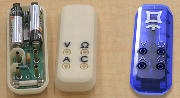
The ohms and the common terminal should be swapped for convenience. You can’t measure volts with a 0.75″ dual banana plug on this one. That is essential as all BNC to banana adapters are made that way as well as any other custom probing solution one could come up with. Amps are never spaced at 0.75″. Most of the time multimeters are arranged like this:
A mA COM V/R
or
A V/R
mA COM
If I don’t win one…I’m buying one….
– Frank Vigilante