
So you have a 3D printer and need to print something of your own design. That’s a problem if you don’t know how to create and edit 3D objects. In this post, we’re continuing our previous misadventures with Blender by making a ‘thing’ torn from a very old book on drafting.
Previously, we’ve made the same part in other 3D design packages. Here’s some links to those other ‘Making a Thing’ posts:
We’ve already done half the work to make a ‘thing’ in Blender, so now it’s time to finish the job. Check out the rest of the tutorial below.
Our Thing
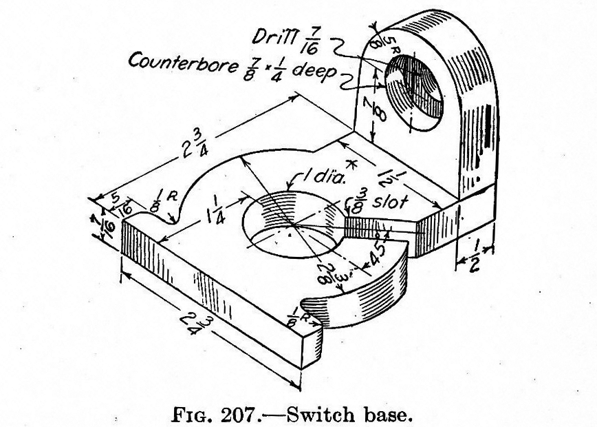
To the right is the ‘thing’ we’re making for all these 3D Printering tutorials. It’s taken out of the 4th edition of Engineering Drawing (French, 1929, p. 105). Yep, it’s an 85-year-old drawing with fractional inches. It serves our purpose, though: a template with which to make something with a 3D CAD package.
By the way, if anyone out there has a 1st edition of Engineering Drawing, I’d love to see if this object actually goes all the way back to the 1911 volume.
The Curse of Blender & What We’ve Done So Far
In the first part of this tutorial, I said using Blender to create a simple mechanical object like our ‘thing’ is akin to using a bulldozer to build a sandcastle. I’m still standing by that assessment. If you want to make precise mechanical parts, don’t use Blender. Blender is a tool for organic and sculptural forms. Want to print out a plastic tree? Blender is a great tool. Want to model some Greek and Roman statuaries? Blender is a great tool. Need a part for a mechanical device? Don’t use Blender. It’s not the right tool for the job.
In the first part of this tutorial, we took a look at the idea behind Blender – mesh editing – and how to interact with vertices, edges, and faces to make a thing. With all the introductory stuff out of the way, it’s time to finish the job.
More Building Of A Thing
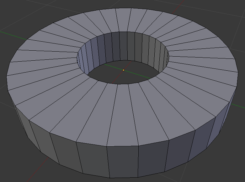
To the right is where we left off with the last part of this tutorial. It’s basically just a washer, but the dimensions are correct for the thing we’re making. There are a few things we need to do before this ‘thing’ is done though:
- Add the 3/8″ slot on this washer
- Add the 2 3/4″ wide flange thingy
- Add the 1 1/2″ wide flange
- Build the mounting bracket with the countersunk hole
Not too bad, and we can do these piecemeal.
Adding the 3/8″ Slot
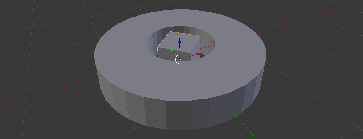 The first order of business is going into object mode and creating a cube with Add -> Mesh -> Cube on the top menu. With the rotate and scale commands on the right hand toolbar, manually set your cube to be 3/8″ in the X and Y axes, and 7/16″ in the Z axis. Then rotate it 45 degrees around the Z axis. You should end up with something like the pic to the left.
 Using the extrude command (hotkey ‘E’), pull one face of the cube through our washer/cylinder. It doesn’t really matter how far, because now we’re going to do something amazing: Boolean operations.
By this point you should have two objects in your top right hand toolbar: A cube and a cylinder. Now we’re going to subtract the cube from the cylinder using a modifier.
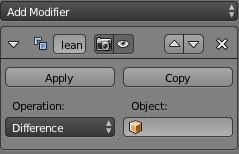 Click on the little wrench icon seen above and select Add Modifier. Select Boolean and you’ll see something that looks like the pic to the right.
In Blender, you can do Boolean operations like Union, Subtract, and Intersect. There are, however, a few limitations. Each Boolean operation only divides up faces and edges, meaning you need to go in and manually delete all the extraneous edges after the operation. Also, the Subtract operation doesn’t put in the missing faces we’ll see once we subtract out the cube.
Subtract the cube from our cylinder. After deleting a whole bunch of faces and edges, and creating the ‘inside’ of our 3/8″ slot, we get something that looks like this:
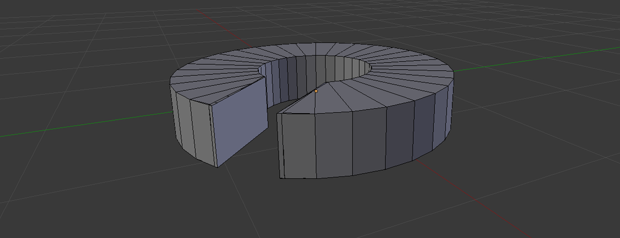 It’s not perfect, but there it is. There are still a few holes in this mesh, but we can fix those later.
Adding The Flanges
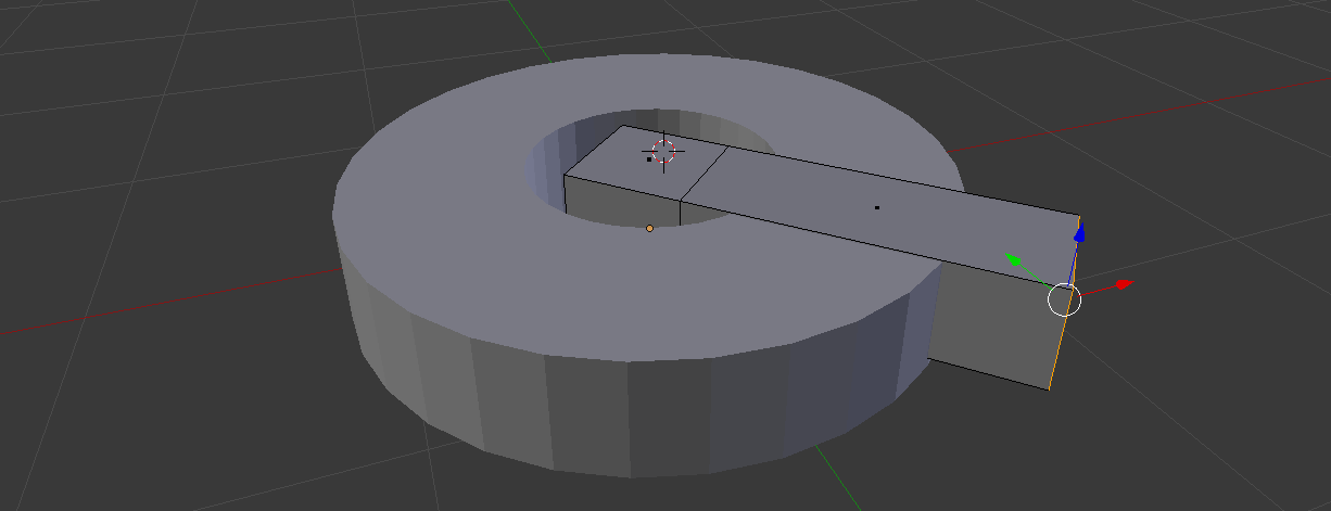
Our thing has two flanges coming off the ‘washer with the slot’ we just made. To create the flange that’s 2 3/4″ wide, Add a cube mesh in object mode and play around with the Scale (hotkey ‘S’) and translate tools. The left hand toolbar will allow you to move and scale this cube into something resembling the larger flange on our ‘thing’. After that it’s a simple matter of doing another Boolean operation (this time ‘Union’) and making something that looks something like this:
That looks just about right for the first flange, but we’re missing the radii on a few corners. That’s not a problem, though, because the Bevel tool exists.
In Edit mode, select one of the outside corners of our new flange. Hit CTRL-B and you’ll be able to set the radius of the bevel with your mouse and the number of segments of the bevel with the scroll wheel. No, you can’t specify a radius, which is just a tiny part of what makes Blender terrible for mechanical design.
Now, extrude two faces of our cylinder out (we’ve completely given up on dimensional accuracy, if you haven’t noticed), and bevel two edges on your new extrusion. In the end you should have something that looks like this:
That’s close enough to the orthographic drawing of our ‘thing’. Yes, there are holes in the mesh but we can fix those later.
The other flange is easily constructed in the same manner as the first.
Putting that dome and counterbore in
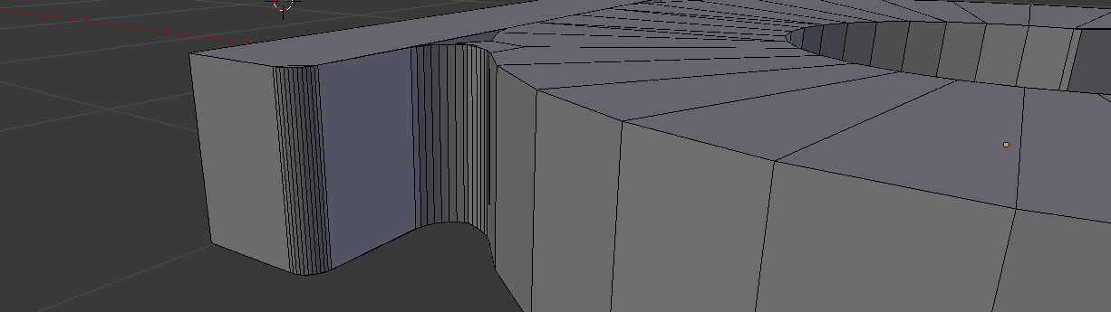
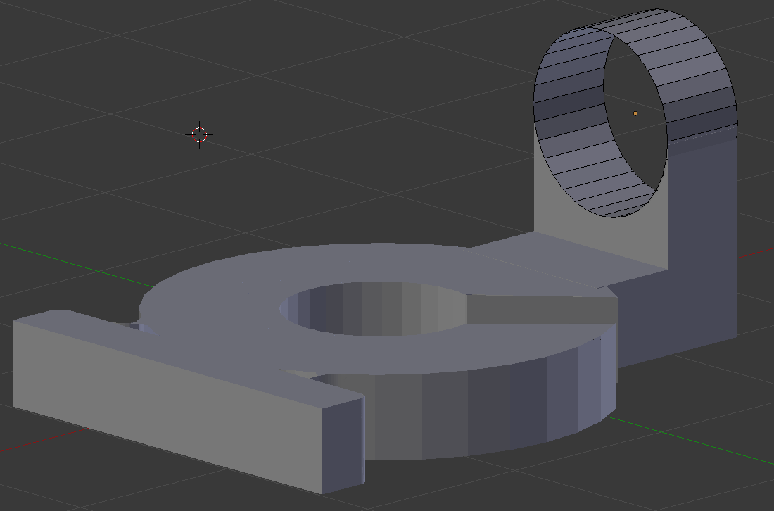
The last bit of our ‘thing’ to build is the weird rounded part with the hole and counterbore up top. Start by extruding our second flange up the necessary amount. Next, create a cylinder in object mode and Boolean-ing the two together. After deleting the faces on the cylinder, you’ll end up with something like this:
There’s one thing left to do: put a 7/16″ hole through the faces we just deleted, and put a 7/8″ counterbore on that hole. Basically, we’re making another torus/washer-type object. Check out the first part of this Blender tutorial for instructions on how to do that.
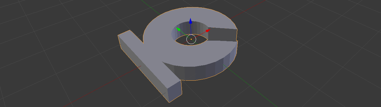
Finishing off the second cylinder/counterbore, we could call this part somewhat complete. Here’s what we ended up with:
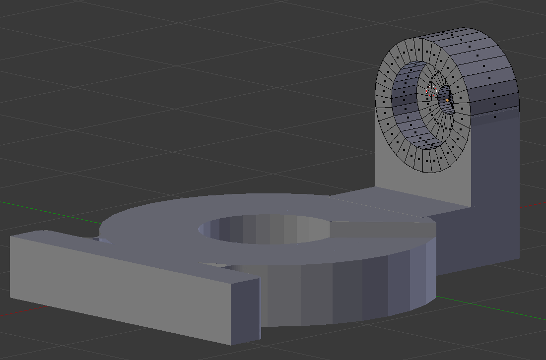
This isn’t to say this part is ready to head over to a printer, though: there are still a few holes in our mesh which will crash any slicing program. This can be fixed with MeshLab, but that’s a tutorial for another time.
Well that’s over with.
That’s how you make a ‘thing’ in Blender. It’s not pretty, but you can do it. Once again, I need to reiterate that Blender was the wrong tool for this job. If you’re making objects to put in a video game, Blender is a great tool. If you’re doing something that could be considered digital sculpture, Blender is a great tool. If you’re making something with straight lines, dimensional parts, and precise angles, you can do far better with one of a hundred different CAD packages.
Concerning next week’s tutorial, it’s a tossup between Solidworks or Sketchup. If you have a preference one way or another (or even a third option), leave a note in the comments.


I really enjoy working with FreeCAD on a daily basis. It is Open-Source, has a nice Python API, is fully parametric and supports many formats for import and export.
+1 for FreeCAD.
I mean, I personally use SolidWorks (FreeCAD is still too rough to replace it), but you can’t go wrong with free-as-in-beer and free-as-in-speech.
Blender also is free and opensource. Each funktion can be used using python, you can expand the functionality with python, and there are thousands of free addons for all kinds of stuff (take ‘Boltfactory’ as an example). You can export your meshes into obj or stl and about three dozend different formats. Its correct that you dont need it for your mechanical designs but it doesnt hurt either. Blender runs on all main plattforms, is very compact (less than 100MB) and is capable of many tricks, like physical simulations and morphing objects, animations and stuff.
Using Autodesk-CAD and Blender(for about 9 and a half years now) personally I prefere Blender a lot. I think its easyer to use(heck, you even have an interactive searchbar) and if you are bored you can use it to make films or even games.
So there is where to get it: http://www.blender.org/download/ and that is where to get help: http://blenderartists.org/forum/
The reason the mesh has holes in it is because you made it wrong/didn’t bother to fix duplicate vertices as you went along.
A mesh editor is perfectly capable of modelling mechanical parts if you get your head around the fact that it’s a mesh editor not CSG.
I avoid using the boolean modifier as much as possible because it generates really ugly unmanageable meshes that are almost impossible to then edit.
As it happens I’m modelling something in blender at the moment. While it’s still missing some small details the main geometry of this case part is there and pretty much all accurate to 0.05mm here’s the latest render of the model: http://alistairtesting.no-ip.org/blender.png
I agree this was a bad way to do it, but if Benchoff were to do it the right way, this tutorial wouldn’t take two parts. It’d take 3 at least, if not 4. Mesh modelers consume a lot of time and effort when you need to be precise.
That being said, this would be a great opportunity to do a tutorial on using Blender’s 3D printing tools to clean up geometry like this.
Pronouncing software rubbish for a job because you don’t know how to use it effectively is one thing (and common). Publishing a tutorial on the wrong way to use it is just annoying. I am far from a blender expert – I don’t know all the shortcuts, it takes me longer than it should to do things cause I have to keep looking stuff up.
I think most of the trouble comes from trying to model some of it by mesh editing (the non-manifold washer in the first part!) and CSG like modelling using booleans in the second.
Blender has no chance of making a clean cut through your washer and filling in the faces if you ask it to cut through a non-manifold mesh.
http://i.imgur.com/tvI7kMj.png
It took only a few minutes and 4 operations, it has proper geometry, can be easily turned into 2D blueprint with dimmensions, will work fine with CAM software etc..
If you have access to Solidworks, if you know how to use Solidworks…then you should use it. T’would appear a 12 month student license is only $100.
@mac
I’m pretty sure ojpg was pointing out just how bad mesh modelers are at this kind of thing compared to feature-based solid modelers. It’s not necessarily SolidWorks in and of itself.
This isn’t a complex model. FreeCAD can do it in much the same way. If you can’t afford software that’s several thousand dollars for a full license, or you strongly prefer to use libre software, it’s a good option to try.
Hey, you’re preaching to the choir on people who denounce a program just because they don’t understand it.
In Part I, Benchoff could’ve finished with a bridge to make the mesh airtight, and his booleans in this section would’ve worked (at least up to the part that he tried to make the second hole). Of course, having access to the bridge tool involves going to the Addons menu in User Preferences and checking the Loop Tools add-on, then saving your preferences. Not at all difficult, but not obvious either.
Though, I still wouldn’t have done it that way, because the mesh is sure to get too messy to edit by hand — you start doing booleans, you’re doomed to stick to booleans unless you want to spend heaps of time cleaning up your mesh.
That all of these things are considerations, though, is why I don’t believe Blender (or any mesh modeler, for that matter) is that well suited to a task like this. The fact is, mesh modelers slow you down (or severely limit you in the case of Sketchup) — they’re not built to be precise, even if you can work precisely in them. No matter how many people say they do mechanical work with Blender, it doesn’t change Blender’s lack of competence at that task.
With a proper feature-based solid modeler, even a simple one, you would:
1. Roughly sketch out the top view of this model
2. Add your dimensions and constraints
3. Extrude it up to the thickness of portion that lies flat
4. Set your working plane to the rear face of the part
5. Sketch out the shape of the vertical portion
6. Add your relations, constraints, and dimensions
7. Extrude the thicker portion out as far as it has to go
7a. Boolean union if it doesn’t happen automatically
8. Go back and extrude the smaller hole to the thickness of the counterbore
9a. Add fillets if you haven’t already done so in your sketches
… And you’re done. And this is assuming there aren’t specialized features available, like a hole feature with counterbore option — if you’ve got a CAD program that can do that sort of thing, you can do this in two or three fewer steps. Dealing with mesh geometry doesn’t ever factor into that kind of modeling — it just works. If you ever need to make a change, your features are still right there, fully parameterized, and thus easy to go back and modify.
Consider that Sinclair case you’re working on. What would you do if you wanted to alter that toothy pattern running along the bottom? What if your screw holes don’t line up with the top piece due to some oversight? What if your bosses aren’t the right size? There are any number of things that could go wrong or might need changing with a change in design requirements. In a feature-based modeler, you can simply alter a dimension here or there. Blender will not be so kind.
well said, while it is possible to use mesh editors for mechanical modeling this seems less a case of a something (software) being bashed because it’s not understood, but a case of it being defended because the users don’t understand why other tools are more appropriate and efficient.
Oh all of those things have already happened more than once :)
The answer is you kick yourself and fix them ;)
Yes blender is probably the wrong tool for the job if you’re trying to design a case or whatever. Having holes in your mesh isn’t blender’s fault though, it’s user error.
Good choice of color – black. This really shows the 3D contour/surface/edge highlights. NOT!
I agree with Alistair. I make viable accurate mechanical parts with Blender regularly. And they are manifold so they work fine with my 3d printer. I also make accurately placed assemblies of mechanical parts for visualization.
i routinely loosen or tighten nuts with my multi tool, it works great, but if i want to tighten something to a particular torque, really crank it down, not ding up the nuts, or do it faster, i use a socket or apt wrench. those aren’t ideal to carry daily though. just because something CAN do something acceptably doesn’t make it the ideal tool for a task. both have their purpose.
for many users, blender is perfectly acceptable, just as my pocket gerber is super useful and available, but it’s not the most appropriate tool for the tasks, it happens to be the one at hand.
in a discussion of multiple tools to accomplish the same task, understanding the short comings of each and why one would choose a particular tool over another for a particular task is critical to improving one’s craft and quality of output.
I can see your point but I still agree with mac and Alistair. There certainly are things you better build with other programms but most mechanics you will ever touch are done just as easy in Blender.
I think it has been mentioned before, but I would really like to see one of these for FreeCAD.
Played around with 0.13 my self, but found it a little unfamiliar/unintuitive, but it looks like others are having much more luck than I.
+1 for FreeCAD. FOSS options should be the priority for lessons with a 3D printing focus. This is largely an open-source movement, after all.
The 0.14 development branch of FreeCAD, while a bit buggy in some areas, is becoming a quite a nice package for single-part designs (well, on 64-bit Ubuntu, that is – can’t speak for other platforms). The dev-assembly branch is coming along nicely, too, but is no where near ready for daily use.
IMHO, FreeCAD’s workflow is comfortably familiar, speaking as a decade-long user of the major commercial CAD offerings (Catia, Pro/E, Solidworks).
SketchUp please!
I would like to see one for sketchup as it seems to be the one used most by all the people I know with a 3d printer, so to me seems like a leader in this realm.
We’ve got a copy here at my work of the 1911 edition. I’ll have to check it out tomorrow.
Awesome!
This part does not appear to be in the 1st edition.
if you’re going into the parametric modelers (Solidworks, Inventor, etc.) it might be a good idea to say what they’re good at and why they exist — i.e. correcting mistakes, creating part variations, and that kind of thing. The tools hit on so far turn ugly when the part so painstakingly made doesn’t quite fit.
Designspark mechanical next!
One thing that blender is great for is animating the interaction between mechanical parts. If you are printing an assembly of parts (gears etc.), Blender can provide some insight into how the assembly will work without having to run prints multiple times.
Solvespace can do the same thing AND is a solid modeler. (And it’s free/open source.)
The term “solid model” is just short for “a mathematical representaion of an object that is aware of inside, ouside”. That, in conjunction with physical properties allow the caculation of things like center of gravity, radius of gyration, etc. Not many modern modelers lack this. That’s how Blender does physics like wave motion and gravity, curved acceleration, etc. FX.
Strictly speaking, that’s true.
But, when people refer to solid modelers, they typically mean a modeler that generates geometry based on dimensions, constraints, and features, and not based on a mesh of vertices and straight edges. Blender doesn’t fall under that umbrella.
As Luke said, Blender is Mesh based. This also has consequences when creating a 3d print. If the print isn’t “watertight” (all the corners of the mesh aren’t connected) then you will have printing errors. Solid modelers don’t have that problem.
Damn, I forgot all about SolveSpace! That is a neat package. I just wish it had Mac and Linux versions.
Does anyone else see a lack of taper?
Nice to see it .
I would like to see FreeCAD next
+1 For sketchup. My understanding is that SketchUp is a surface rather than a solids modeler and so it’s output doesn’t translate to 3D-printing well. So I’d like to see focus on the back-end of converting a SketchUp drawing to something printable rather than on how to draw in SketchUp (this topic has been covered in detail on other sites).
Since i’m totally new to 3d modelling, and wanted to see if I could manage to build simple stuff, in case i eventually buy a 3d printer, I started to look more at the 3d printering column. SInce I will never afford AutoCad, and Blender scared me after the first article, I went with someone’s comment and tried Sketchup to replicate the Switch Base. After watching a few of googl’es own tutorials It wasn’t really long before I made the model, But there is a dimension on the drawing that I do not understand.
The 5/8″ radius mentioned on the top flange refers to what? The radius of the dome should be 3/4″ since the width of the base is 1 1/2″ , and the sides appear flush with the base. Also, in the Making A Thing In AutoCAD, Part II article, we can see Brian setting the dome radius to 0.7500″. No dimension equals to 5/8″ the way I have built it, there is a 5/16″ offset around the dome though. Can anyone explain? I added my work below.
http://i.imgur.com/VS2YlBo.jpg
https://drive.google.com/file/d/0B1dbGJRJrE30ZGdtbWhlRXBUNlk/edit?usp=sharing
There is a taper hidden there. Good eyes Dude Love :)
I know that you’ve already done some work in figuring out sketchup.
But seriously give Creo-Elements a go.
It might sound strange to someone who appears happy with sketchup, but Honestly I found sketchup a huge pain, often finding it awkward to understand what part of a large object you’re looking at, difficult to measure any part after it’s drawn, you can put down shapes that you think are together, but then it turns out they might be together on a x/z axis, but they are all over the place on y and don’t touch!
Then you’d find missing faces and not solid objects, or when trying to make a solid object you’d end up with a hollow, when trying to make a hollow object you’d end up with a solid, trying to group faces was often an exercise in frustration, deleting lines etc…
To be honest, sketchup might be free but it’s only good value if you place no value on your time. (so for the next tutorial, maybe a sketchup one would be good to show me why I am wrong).
and without the ability to properly group parts as assemblies that can be hidden etc, it’s utterly useless at designing a complex machine. (or maybe I was just utterly useless at using it?!)
Nearly a year ago I wrote a series of tutorials on my own blog about making gears in Creo elements
http://ah-screwit.blogspot.co.uk/search/label/CAD
The reason that I did that was that I was finding it pretty difficult to find anywhere online that actually explained how to do this, some people appeared to be drawing every tooth on a gear, (this is what you’d have to do in sketchup?)
To a greater or lesser extend, that particular program works just like the original autocad tutorial, draw a 2d shape and then make it 3d by pulling it either up or down…
Perhaps… just as an idea…
These tutorials are good, the series has been good.
I’m just as guilty as anyone of having said, you didn’t use [insert my favourite] program, or blender isn’t a good machine part design tool, or AutoCAD is ridiculously expensive and not aimed at home users etc…
but given the people on here saying “you should have done this” or “you shouldn’t have done that”, “the correct way to…” -arguably because Blender is a very complex program.
Maybe the HAD staff could run a competition or some sort of event for creating these CAD tutorial articles.
find an old patent drawing (like they have done here) and say, if you have a favourite CAD package, then why not share how to use it. by drawing this.
Also a brief pros/cons list.
e.g. pro – works with DXF (import only), pro exprt to STL, cons cannot save as DXF, con cannot group objects as assemblies, Pro – free for home and educational use, con not free for business use. etc
There are too many free, or nearly CAD packages, with too many “features” and “restrictions” that it’s really impossible for any one person to try them all.
This would be a way, (might be good might be bad, but it’s a way) that hackaday could get a shed load of essentially user reviews from people who are using the software almost day in day out.
This tutorial, the comments on this tutorial, and the fact that at least 2 of the holes in the mesh are clearly visible on the finished part, that in it’s current state it would essentially be unprintable and crash the slicing software (it’s a useless drawing of a useless object!), well it sort of goes to show that one man just cannot master all CAD programs. -so why not draw from the user base?
And how much would the article writers be compensated, chosen or not? Hackaday is a commercial site, not a non-profit. Crowdsourcing for profit is evil, and shouldn’t be done — you’re essentially stealing man-hours while pitting peers against each other.
how much were people compensated for their comments above telling the “proper” way to do it?
how much are people compensated when they complete a project, write it all up and hackaday link to it?
how much are Linux Kernel developers compensated when their work is put into commercial releases?
It’s a personal choice.Clearly you feel that without getting paid you would not contribute…
Hackaday would make cents from a few ad displays, whilst readers would get a broad overview of more CAD packages that Brian could ever look at on his own, whilst at the same time those users would have more in depth knowledge than Brian could get in any reasonable time whilst also doing his day job.
Any article written for Hackaday would be proprietary to Hackaday. That’s the key difference. Comments remain the sole opinion of the individuals posting them, and are not the property of Hackaday. Contributions to a free/libre software project are owned by the community, and everyone benefits from one another’s contributions.
So, again, if we’re to give something to Hackaday, which is a commercial entity and is the only entity that would be making money off of these contributions, what do we get in return?
And let me be clear, if Hackaday’s terms of service explicitly asserted ownership over what I write in the comments, I would not be commenting at all.
Really? It’s amazing that you are aware of what publishing and sender shop rights are going to be attributed to a scheme that at the moment remains just the crazy idea of one idiot in the comments section (me)
Suffice to say there are plenty of available exclusive, and non exclusive, publishing agreements, with or without attribution. It is not certainly the case that you will be giving your work to hackaday and let go of all your rights to your work!
Also, fine, I get it. You wouldn’t contribute to hackaday or community in anyway. (You also have Adblock turned on I’ll bet?)
That does not mean that others won’t be happy to put in either time or effort to help educate others…
I don’t think you’re understanding something. Hackaday is a blog / news outlet. It’s a commercial project. They make money off it. Even if I have the rights to republish it, it’s still Hackadays property, even if only in part. I won’t give them anything if I don’t get my fair share for my efforts.
Hackaday is not a community. Okay? Do you hear me? I’ll repeat myself. HACKADAY IS NOT A COMMUNITY. Contributing to it is just giving free labor to a corporation with nothing in exchange.
I have no qualms and in fact do contribute to community projects. If Hackaday would start and spin off a community project, run by the community, which publishes all items under copyleft license (like the CC BY-SA or the GNU FDL), and would be completely independent of Hackaday’s commercial interests, I would have no problem contributing to it.
One good example is the Controller Project by former writer Caleb Kraft. I haven’t found the time to contribute to that (yet), but that’s a solid example of something I could get behind.
And no, I don’t run Adblock. My demand for fair compensation goes both ways. If Hackaday wants to run ads for revenue, I’ll let those ads show up so they get that revenue.
Seriously, this is all not a difficult concept to grasp. Crowdsourcing for commercial projects is evil. Copylefted community-run projects are kosher. It’s really that damn simple.
So you’d hate the though of granting a non-exclusive license to republish, where you retain rights and ownership.
But you’d gladly release under Creative Commons or copy left where you freely give your content, allow hack a day to profit, and allow anyone else to copy and profit too?
Either you have the reading comprehension of a fourth grader, or you’ve nothing left to say and are just taking half-witted pot-shots at this point. Assuming it’s the former, allow me to lay this out as clearly as I can.
First off, I have no problem with a site like Hackaday having full or partial ownership of what I write. The thing is, I need to be paid for that to happen. I won’t just work for free; it takes a special kind of stupid to do that. I’d similarly have a problem if a site such as this one would exploit people in the aforementioned manner; just because people should know better than to walk into a scam doesn’t justify a scammer.
Moreover, I highly doubt a site such as this one would allow you to retain the rights to a work granted to them beyond use in a portfolio. So if we’re talking realistically, it wouldn’t be non-exclusive and I wouldn’t be able to republish.
As for community projects: You retain the rights under a copyleft license, and you’re fully permitted to release it under multiple licenses. Do some more research, okay? (And furthermore, I specifically stated CC BY-SA. That’s a strong copyleft license. It’s not a separate category.)
The reason I would only accept a copyleft license is that all changes would likewise need to be contributed back to the community. That’s in contrast to a permissive license that would allow a third party to make a copy and lock people out from copying or editing that document. So, a commercially run website could certainly republish the article with appropriate citations, but they wouldn’t be able to capitalize on it any further than that without negotiating a different license; if it should be included, for example, in a compendium alongside proprietary works, I’d have grounds to sue. At minimum, I’d probably get my lawyer to write a scary letter.
Basically, if I want to put something in the hands of a community, I’d also include a mechanism to keep it there.
And let’s be real here: whether it’s released under a copyleft license, or if it’s given to Hackaday under a non-exclusive license, a tutorial or three won’t earn me much money in my own hands. I’m not a professional technical writer, so I don’t have many articles to show; I don’t have a big presence on the Web, so I wouldn’t get much traffic; and upkeep of those articles would probably cost more than I could earn.
A site comparable to Hackaday stands to earn much, much more revenue than any tutorial contributor could stand to make on their own, which would make crowdsourcing doubly evil. Not only would it amount to theft, there would be enough of a difference in profit potential that such theft could never be justified.
Now, I’ve written much more than was likely justified. I’ve said what I needed to say, and articulated it as clearly as I could. I’m not going to get sucked into a childish pissing contest, so if you refuse to do your due diligence, that’s just too bad for you.
Not sure about Engineering Drawings 1st edition, but the 3rd edition has that part in it on p92.
@ Brian Bencoff concerning ” No, you can’t specify a radius, which is just a tiny part of what makes Blender terrible for mechanical design.” you got something wrong there. First of all: you can just type in the ammount of offset that you want.
Second: after confirming by pressing enter or LMB in the ToolsPanel the last used operator pops up, to make changes and stuff. In this case you will find the AmountType, the Amount, the Segments, the Profile (0.5 = circular convex), the option to use bevel only on vertices, not on the edges, and even a Material-Slider.
If you dont find the Tools-Panel, with the mouse over the 3D-Space press T. The ToolsPanel should now pop up on one of the sides inside the 3D-Space(usually on the left side). Pressing T again will hide it.
So now that you know you can precisely set your numbers, would you kindley correct your error in the Tutorial?
By the way: There is a SPIN-command too (alt-R).Be aware thow that it uses the 3d-cursor (the red crosshair) as center of rotation. Best regards.
From whatever little understanding I have got: 1stly dimensioning is possible in Blender. But that necessitates a lot more steps on an average.as for example drawing an tangent to an arc, trimming of unnecessary parts of a line, making a point snap onto a line ,making multiple points symmetric to a line, making a curve parallel to another curve are only very few examples of things that can be done on CAD programmes in the blink of an eye while they would be cumbersomely doable in Maya,Max,Blender ,Modo or whatever design programmes. 2ndly if you are making something whose inappropriate dimensioning is not going to lead to catastrophic outcome, you will not perceive the necessity of dimensioning. As for example if you make a bowl, Blender’s mesh checking capabilities will ensure that it gets 3d-printed properly. But if you are going to produce many parts of a machine that’s constrained by one another on a millimetre level, probably you will notice some deficiency of the 3d design programmes whatever it is.3rdly NURBS is not going to retire so soon. It may have fallen out of favour in 3d designing or prototyping but there are reasons they remain to get used so vehemently in car design, aerospace design or for that matter any design necessitating exact measurements because mathematically robust enough NURBS engines can present each and every point of a surface in a very precise way that’s tough to achieve even in hugely subdivided meshes.4thly things are changing quickly. Many CAD software are achieving the capability to model in 3D while for Blender there are upcoming scripts that are introducing CAD tools slowly buy surely. So there is no place of qualms between us when they software makers themselves are aware of the core functionality and design goal of their software and also for what purpose they are not intended.I have never heard any Blender,Maya,Max developer bragging about their CAD capability nor I have heard any CAD software developers bragging on about how their apps can be used for organic form or 3d arts purpose.But gradually their tools will get merged and we will be in for a great time.AHEM!!!