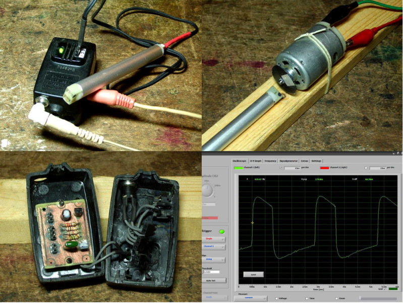
We love writing up projects that re-use lots of old parts. In fact, we save the links and use them as defense when our significant other complains about the “junk” in the basement. No, that tactic hasn’t ever worked, but we’re going to keep trying. Case in point, [Wotboa] needed a non-contact tachometer. There are plenty of commercial products which do just that. After consulting his parts bin, [wotboa] realized he had everything he needed to hack out his own. An IR break beam sensor from an old printer was a perfect fit in an aluminum tube. With the outer shell removed, the emitter and detector were mounted in the nylon shell of an old PC power supply connector, effectively turning them pair into a reflective sensor. To amplify the circuit, [wotboa] used a simple 2n2222 transistor circuit. The key is to keep the voltage seen by the sound card the range of a line level signal. This was accomplished by adding a 2.2 Megohm resistor in line with the output. [wotboa] drew his schematic in eagle, and etched his own PCB for the project. Even the tachometer’s case came from the parts bin. An old wall wart power supply gave up its shell for the cause, though [wotboa] is saving the transformer for another project.
For sensing, [wotba] used [Christian Zeitnitz’s] Soundcard Oscilloscope software. Measuring the RPM of the device under test is simply a matter of determining the frequency of the signal and multiplying by 60. A 400 Hz signal would correspond to a shaft turning at 24,000 RPM. The circuit performs well in the range of RPM [wotboa] needs, but using a sound card does have its limits. The signals on the scope look a bit distorted from the square waves one would expect. This is due to the AC coupled nature of sound cards. As the signal approaches DC, the waveform will become more distorted. One possible fix for this would be to remove the AC coupling capacitor on the sound card’s input. With the capacitor removed, an op amp buffer would be a good idea to prevent damage to the sound card.
[Via Instructables]


there are plenty of cheap ( <$3 ) USB sound cards that could be used for this. some don't even have decoupling caps!
Proof reading must be a lost art.
FYI: No one has printed a whole toilet seat on a 3D printer.
FYI that statement has nothing at all to do with this article.
or donuts…
Hummmmm, taco meters.
Another solution around the low frequency response is to modulate a high frequency (15kHz or so) carrier. That can be done with a 555 or even a few transistors. For extra credit, power the whole circuit from the bias voltage intended to power microphone preamps.
just plug a photocell right straight into the sound card input:
http://lalob.info/?page_id=66
they use audacity for their signal analysis, much more hackerly than the non-free ‘Soundcard Oscilloscope’
It is free for non-commercial use though. Which is pretty much free.
Although open source is always better of course.
I miss the fact why you have to multiply it with 60… Nice hack :)
It’s to convert from revolutions per second to revolutions per minute.
Of course! I overlooked the per second and per minute notation…
I don’t think the decoupling / poor signal shape matters. You only need the frequency, just count the zero crossings. Simple.
I like this idea, now I just need to mount my old PC with its sound card and monitor onto my riding mower so I can monitor the engine’s RPM! B^)
(nice hack BTW)