The Tachometer Inside Your Smartphone

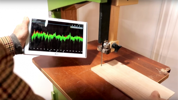
It’s the latest in instrumentation for the well-appointed shop — an acoustically coupled fast Fourier transform tachometer. Sounds expensive, but it’s really just using a smartphone spectrum analyzer app to indirectly measure tool speeds. And it looks like it could be incredibly handy.

Normally, non-contact tachometers are optically coupled, using photoreceptors to measure light flashing off of a shaft or a tool. But that requires a clear view of the machine, often putting hands far too close to the danger zone. [Matthias Wandel]’s method doesn’t require line of sight because it relies on a cheap spectrum analyzer app to listen to a machine’s sound. The software displays peaks at various frequencies, and with a little analysis and some simple math, the shaft speed of the machine can be determined. [Matthias] explains how to exclude harmonics, where to find power line hum, isolating commutator artifacts, and how to do all the calculations. You’ll need to know a little about your tooling to get the right RPM, and obviously you’ll be limited by the audio frequency response of your phone or tablet. But we think this is a great tip.

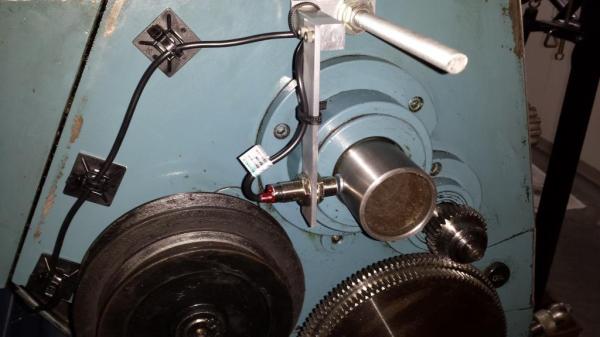
[Matthias] is no stranger to shop innovations and putting technology to work in simple but elegant ways. We wonder if spectrum analysis could be used to find harmonics and help with his vibration damping solution for a contractor table saw.

Continue reading “The Tachometer Inside Your Smartphone”

Lathe Tach

Excuse Me, Sir. Do You Know How Fast Your Lathe Was Traveling Back There?

When machining metal, it is important to know how fast the cutting tool is traveling in relation to the surface of the part being machined. This amount is called the ‘Surface Speed’. There are Surface Speed standards for cutting different types of materials and it is good practice to stick with those standards in order to end up with a good surface finish as well as maximizing tool life. On a lathe, for example, having a known target Surface Speed in mind as well as a part finish diameter, it is possible to calculate the necessary spindle speed.

Hobbyist [Paul] wanted a method of measuring his lathe’s spindle speed. Since spindle speed is measured in RPM, it made complete sense to install a tachometer. After browsing eBay for a bit he found one for about $20. His purchase came with the numeric LED display, a mounting bezel and the all important hall effect sensor. The Hall effect sensor measures changes in a magnetic field and in turn varies its output voltage. [Paul] fabbed up an aluminum bracket that supports the sensor just off of the rear of the lathe spindle. A magnet was then glued to the outside diameter of the spindle below the sensor. The once per revolution signal is generated every time the magnet passes the sensor while the lathe is running. The display was mounted to the lathe near eye height by means of another aluminum bracket and case.

After a little work, [Paul] can now keep a close eye on his spindle speed with a quick glance over at his new tachometer display while he’s turning those perfect parts! If this project tickles your fancy, you may want to check out this fantastic DIY tachometer or this one that uses a soundcard.

tachtastic diy tachometer

Fantastic Tach Is Strangely Called Tachtastic

We all have projects from yesteryear that we wish had been documented better. [EjaadTech] is fighting back by creating a project page about a tachometer he built 3 years ago while in college. He’s done a great write-up documenting all the steps from bread-boarding to testing to finished project. All of the code necessary for this tachometer is available too, just in case you’d like to make one yourself.

At the heart of the project is an AVR ATMega8 chip that performs the calculations and controls the LCD output screen that displays both the immediate RPM as well as the average. To hold everything together, [EjaadTech] etched his own custom PCB board that we must say looks pretty good. In addition to holding all the necessary components, there is also an ISP connector for programming and re-programming.

There are two attachment options for sensing the RPM. One is a beam-break style where the IR emitter is on one side of the object and the receiver is on the other. This type of sensor would work well with something like a fan, where the blades would break the IR beam as they passed by. Then other attachment has the IR emitter and receiver on one board mounted next to each other. The emitter continually sends out a signal and the receiver counts how often it sees a reflection. This works for rotating objects such as shafts where there would not be a regular break in the IR beam. For this reflective-based setup to work there would have to be a small piece of reflective tape on the shaft providing a once-per-revolution reflection point. Notice the use of female headers to block any stray IR beams from causing an inaccurate reading… simple and effective.

Sound Card Tachometer Rises From The Junkbox

We love writing up projects that re-use lots of old parts. In fact, we save the links and use them as defense when our significant other complains about the “junk” in the basement. No, that tactic hasn’t ever worked, but we’re going to keep trying. Case in point, [Wotboa] needed a non-contact tachometer. There are plenty of commercial products which do just that. After consulting his parts bin, [wotboa] realized he had everything he needed to hack out his own. An IR break beam sensor from an old printer was a perfect fit in an aluminum tube. With the outer shell removed, the emitter and detector were mounted in the nylon shell of an old PC power supply connector, effectively turning them pair into a reflective sensor. To amplify the circuit, [wotboa] used a simple 2n2222 transistor circuit. The key is to keep the voltage seen by the sound card the range of a line level signal. This was accomplished by adding a 2.2 Megohm resistor in line with the output. [wotboa] drew his schematic in eagle, and etched his own PCB for the project. Even the tachometer’s case came from the parts bin. An old wall wart power supply gave up its shell for the cause, though [wotboa] is saving the transformer for another project.

For sensing, [wotba] used [Christian Zeitnitz’s] Soundcard Oscilloscope software.  Measuring the RPM of the device under test is simply a matter of determining the frequency of the signal and multiplying by 60. A 400 Hz signal would correspond to a shaft turning at 24,000 RPM. The circuit performs well in the range of RPM [wotboa] needs, but using a sound card does have its limits. The signals on the scope look a bit distorted from the square waves one would expect. This is due to the AC coupled nature of sound cards. As the signal approaches DC, the waveform will become more distorted. One possible fix for this would be to remove the AC coupling capacitor on the sound card’s input. With the capacitor removed, an op amp buffer would be a good idea to prevent damage to the sound card.

[Via Instructables]